|
Yanmar 2GM20F:
Installation, Alignment, and Hookups
This page was last updated on 8
August 2001.
TUESDAY 7/31/01
 After
spending the morning preparing the engine
beds and using my template to properly set the mounts for the engine
alignment, I drove home to pick up the new Yanmar. Back at the yard, I
reversed the process used to get the old SB12 out of the boat, and swung the
boom out over the side so I could hoist the engine out of my truck and into the
cockpit. This went smoothly, even though I was
"performing" in front of the lunch crowd at the nearby
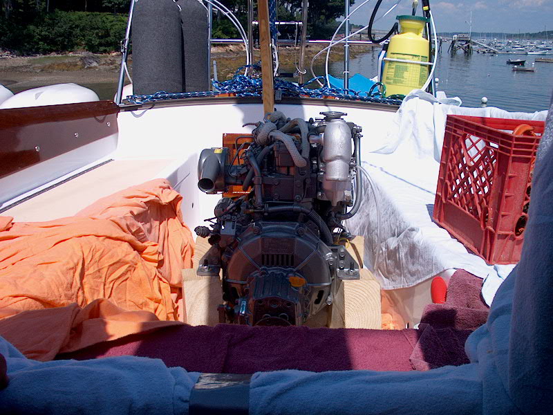
restaurant. As before, I set the engine in the cockpit well, then moved
the hoist forward and raised the engine up to the bridgedeck. Here I
paused, and installed the four flexible engine mounts in their proper
positions. I had marked them before when I was using the template to get
the rough alignment right. After
spending the morning preparing the engine
beds and using my template to properly set the mounts for the engine
alignment, I drove home to pick up the new Yanmar. Back at the yard, I
reversed the process used to get the old SB12 out of the boat, and swung the
boom out over the side so I could hoist the engine out of my truck and into the
cockpit. This went smoothly, even though I was
"performing" in front of the lunch crowd at the nearby
restaurant. As before, I set the engine in the cockpit well, then moved
the hoist forward and raised the engine up to the bridgedeck. Here I
paused, and installed the four flexible engine mounts in their proper
positions. I had marked them before when I was using the template to get
the rough alignment right.
|
|
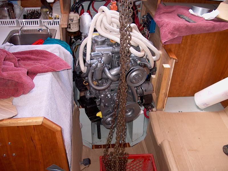 Setting up the hoist one final time, I swung
the engine through the companionway, and lowered it down towards the engine
room. It was easy to move it as required, and soon I had it nearly sitting
on the beds. As I lowered, the forward mounts came into contact with the
beds first, to help me keep things in position I partially installed the two
forwardmost lag screws on the forward
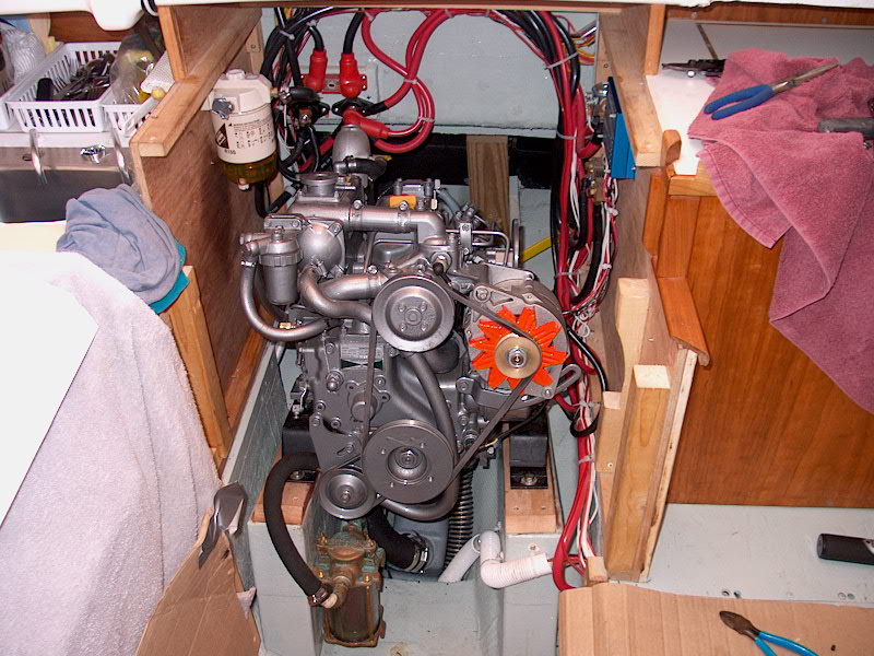
mounts. Then, I continued lowering the engine until the after mounts were
resting on the engine foundation. Note that I had removed the alternator
for two reasons: to make it a little easier to get the engine in place
(without the alternator projecting from the side) and I am replacing the stock
alternator with the high capacity large-frame alternator I used on my other
engine, and around which my electrical and charging systems are
constructed. The 55-amp alternator that came with the engine would be
fine, but it is internally regulated and therefore incompatible with my external
smart regulator. Setting up the hoist one final time, I swung
the engine through the companionway, and lowered it down towards the engine
room. It was easy to move it as required, and soon I had it nearly sitting
on the beds. As I lowered, the forward mounts came into contact with the
beds first, to help me keep things in position I partially installed the two
forwardmost lag screws on the forward
mounts. Then, I continued lowering the engine until the after mounts were
resting on the engine foundation. Note that I had removed the alternator
for two reasons: to make it a little easier to get the engine in place
(without the alternator projecting from the side) and I am replacing the stock
alternator with the high capacity large-frame alternator I used on my other
engine, and around which my electrical and charging systems are
constructed. The 55-amp alternator that came with the engine would be
fine, but it is internally regulated and therefore incompatible with my external
smart regulator.
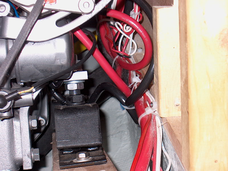
With the engine sitting squarely on all four
mounts, I installed the lags and partially threaded them in. I removed the
hoist and cleared things out a bit to give me room to work. I made sure
that the engine was in the proper place, and that the mounts were all lined up
with the engine--it's easy for them to get cockeyed a bit. I needed a
little crowbar persuasion to get the aft port mount properly aligned so I could
install the after lag screw. Then, I tightened down all the lags, leaving
them only slightly loose so I could move the engine if necessary to affect the
alignment.
|
|
 Moving
into the cockpit, I reached through the access hatch there and pulled the shaft
forward to check the rough alignment. The couplings thunked together
nicely, indicating that the alignment was very close. The side-to-side and
up-and-down alignment seemed spot on, so all I had to worry about was the fine
face alignment of the couplings. Using a feeler gauge, I checked the coupling
alignment all the way around, and made some small adjustments to the
engine. It didn't take much--the alignment template is worth its weight in
platinum, and is certainly worth the effort required to build it. Then, I
cranked down all the lags, and tightened the adjusting nuts on the mounts.
I'll check alignment again once the boat is in the water. Cranking down
the lags required several transmogrifications of my 1/2" ratchet, including
long and short extensions, and no extensions at all, because of the tight access
in some locations. My arms were certainly tired afterwards. Moving
into the cockpit, I reached through the access hatch there and pulled the shaft
forward to check the rough alignment. The couplings thunked together
nicely, indicating that the alignment was very close. The side-to-side and
up-and-down alignment seemed spot on, so all I had to worry about was the fine
face alignment of the couplings. Using a feeler gauge, I checked the coupling
alignment all the way around, and made some small adjustments to the
engine. It didn't take much--the alignment template is worth its weight in
platinum, and is certainly worth the effort required to build it. Then, I
cranked down all the lags, and tightened the adjusting nuts on the mounts.
I'll check alignment again once the boat is in the water. Cranking down
the lags required several transmogrifications of my 1/2" ratchet, including
long and short extensions, and no extensions at all, because of the tight access
in some locations. My arms were certainly tired afterwards.
|
|
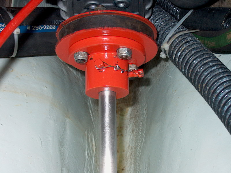 With
the mounts secured, I moved on to install the new Yanmar flexible coupling (Part
# 104214-05450) and
attach the shaft to the engine. I used the new flexible coupling in place
of the Drivesaver I had previously on the recommendation of my engine
supplier--the new one is two slabs of steel surrounding a heavy-duty rubber
core. This absorbs the movement of the engine (the result of the flexible
engine mounts) and will also serve as a sort of "circuit breaker"
should the propeller come into contact with an immobile object--breaking the
coupling instead of the transmission. The flexible coupling features studs
on each side, and I secured it first to the transmission coupling, then secured
the shaft coupling and shaft to the other side, using nylock nuts. Working
upside down through my (thankfully) large cockpit hatch, securing the eight nuts
took over a half hour, leaving me feeling woozy. With
the mounts secured, I moved on to install the new Yanmar flexible coupling (Part
# 104214-05450) and
attach the shaft to the engine. I used the new flexible coupling in place
of the Drivesaver I had previously on the recommendation of my engine
supplier--the new one is two slabs of steel surrounding a heavy-duty rubber
core. This absorbs the movement of the engine (the result of the flexible
engine mounts) and will also serve as a sort of "circuit breaker"
should the propeller come into contact with an immobile object--breaking the
coupling instead of the transmission. The flexible coupling features studs
on each side, and I secured it first to the transmission coupling, then secured
the shaft coupling and shaft to the other side, using nylock nuts. Working
upside down through my (thankfully) large cockpit hatch, securing the eight nuts
took over a half hour, leaving me feeling woozy.
Note that the photos shows my
half coupling and flexible coupling after I repainted them; the red color is not
standard.
|
|
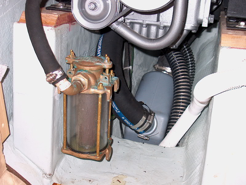 As
I still had some time left in the day, I spent some of it reattaching the
exhaust hose to the engine. Using the same length of hose from the old
engine, I determined a new route for it from the riser, down to starboard of the
transmission, and then forward to the Vetus Waterlock in the bilge beneath the
engine. This is a more direct--and more convenient--route than the hose
had to take with the old engine, and I was able to cut about 12" off the
hose. I secured it to the riser and Waterlock with double clamps. I
also reinstalled my raw water strainer, and attached the short length of hose
needed to run from the strainer to the inconveniently-located raw water pump on
the engine. (It's located on the back side of that pulley above the
strainer--meaning that changing the impeller should take about 9 times as long
as it should. This seems like poor design--I wonder why they did it this
way?) As
I still had some time left in the day, I spent some of it reattaching the
exhaust hose to the engine. Using the same length of hose from the old
engine, I determined a new route for it from the riser, down to starboard of the
transmission, and then forward to the Vetus Waterlock in the bilge beneath the
engine. This is a more direct--and more convenient--route than the hose
had to take with the old engine, and I was able to cut about 12" off the
hose. I secured it to the riser and Waterlock with double clamps. I
also reinstalled my raw water strainer, and attached the short length of hose
needed to run from the strainer to the inconveniently-located raw water pump on
the engine. (It's located on the back side of that pulley above the
strainer--meaning that changing the impeller should take about 9 times as long
as it should. This seems like poor design--I wonder why they did it this
way?)
|
This done, I called it quits for the day,
knowing that I was ahead of my initial aggressive schedule. Things were
going very well.
|
|
|
| Please click here
to continue the project--final hookups of the fuel and electrical systems, and
the cooling system.
|
|