|
Yanmar 2GM20F:
Installation, Alignment, and Hookups (Continued)
This page was last updated on 8 August 2001.
WEDNESDAY 8/1/01
 First
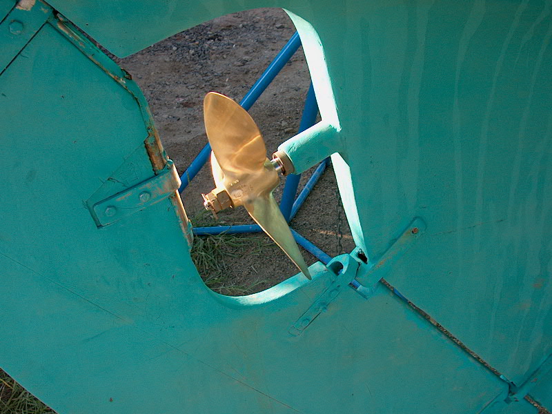
thing today, I installed the new propeller. This is the last thing
remaining that would prevent the boat from going back in the water. The
new propeller is a three blade Michigan Sailer, 12x13. It came from a
different prop shop than my first one did, so it actually showed up on time. First
thing today, I installed the new propeller. This is the last thing
remaining that would prevent the boat from going back in the water. The
new propeller is a three blade Michigan Sailer, 12x13. It came from a
different prop shop than my first one did, so it actually showed up on time.
Now, I moved back inside the
boat--armed with an electric fan today to keep things a little cooler.
It's been warmer each day this week--beautiful, but it gets stuffy inside the
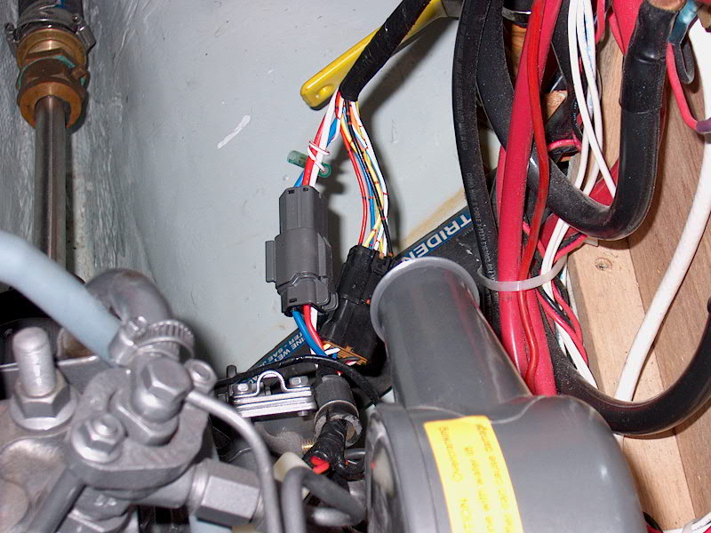
boat, baking in the dry yard. First, I hooked up the new alternator.
I had to put new ends on the wires that come from the engine's wiring harness so
that I could install them on the new alternator. Of course, when I went to
bolt the alternator on, the bolt that was used to secure the original one wasn't
long enough. I couldn't find anything in my spare parts box that would
work, so I had to go out and buy a new bolt to fit. While I was at it, I
picked up a number of other things I needed, including fuel hose barbs, hose
clamps, and a new engine throttle cable. (I'm using the "old"
throttle cable for my new shifter, and needed another cable (shorter) for the
throttle--remember, the old shift cable on the old Yanmar was a heavy duty,
thick one that was incompatible with my new controls. Read more about the
controls here.)
|
|
 With
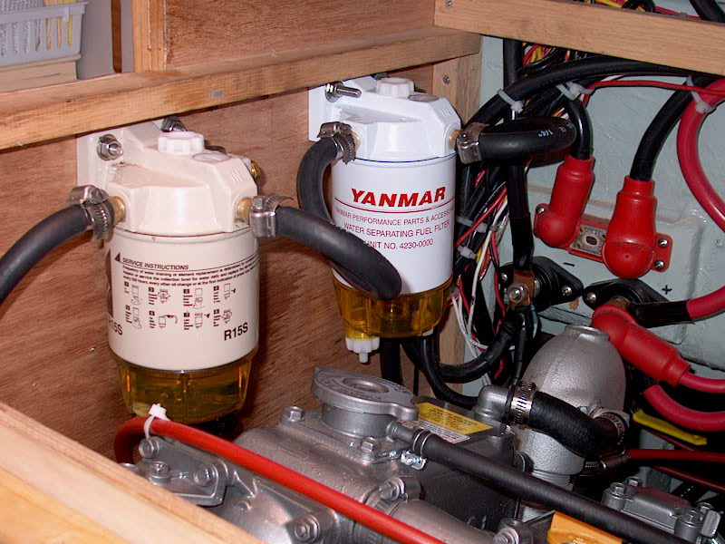
the new materials in hand, I finished hooking up the alternator. Now I
could hook my batteries back up and have power on board again. Next, I
turned to the fuel system. I received a new Racor filter with the engine,
so I decided to install that one in addition to the one I already had
installed. This required moving the original one so that both would fit,
so I removed it and reinstalled both filters next to one another on the side of
the engine room. Next, I rerouted the fuel hose, interconnecting the two
filters and finally connecting to the engine lift pump. With
the new materials in hand, I finished hooking up the alternator. Now I
could hook my batteries back up and have power on board again. Next, I
turned to the fuel system. I received a new Racor filter with the engine,
so I decided to install that one in addition to the one I already had
installed. This required moving the original one so that both would fit,
so I removed it and reinstalled both filters next to one another on the side of
the engine room. Next, I rerouted the fuel hose, interconnecting the two
filters and finally connecting to the engine lift pump.
Because the new engine has a
normal return line (rather than the old engine, which returned excess fuel only
to the engine-mounted filter), I had to reinstall the return line fitting on the
fuel tank. This was an easy job and only took a few minutes. Then, I
connected a final length of fuel hose to the return fittings, secured it out of
the way with tie-wraps, and the fuel system was complete!
|
|
Next, I
moved on to the new instrument panel. First, I removed the old panel
and wiring harness. Of course, never expecting to have had to remove this
panel, I had thoroughly secured the harness with tie-wraps, and the panel was 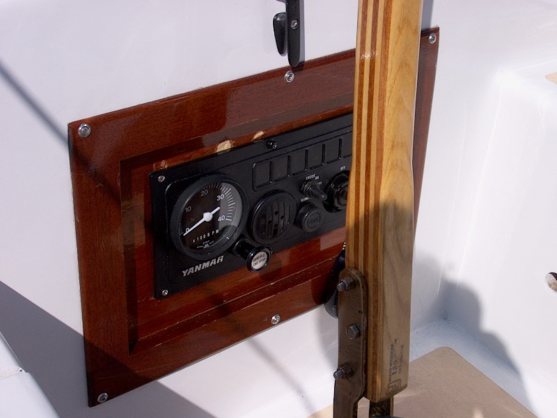 siliconed
in place. It took a little work to remove--I had to cut all the tie-wraps,
and slowly pry the panel away from the wooden backer. The silicone is
tenacious, and I damaged the plywood a little. I guess I'll probably just
make a new piece this winter--but it's OK for now. With the old stuff
removed, I used the rubber gasket that came with the new panel to mark its shape
on the backer, and cut siliconed
in place. It took a little work to remove--I had to cut all the tie-wraps,
and slowly pry the panel away from the wooden backer. The silicone is
tenacious, and I damaged the plywood a little. I guess I'll probably just
make a new piece this winter--but it's OK for now. With the old stuff
removed, I used the rubber gasket that came with the new panel to mark its shape
on the backer, and cut  the
extra out with my jigsaw. Then I installed the panel with screws. I
ran the wiring harness aft from the engine room, through the port cockpit
locker, and plugged the connectors together. Simple. the
extra out with my jigsaw. Then I installed the panel with screws. I
ran the wiring harness aft from the engine room, through the port cockpit
locker, and plugged the connectors together. Simple.
I ran the engine stop cable
through the panel, secured the fitting, and then ran the cable down the
centerline, beneath the cockpit and fuel tank, down to the engine, where I
connected it to the stop lever--the wire just passes through a clamping fitting,
and you screw down a setscrew to secure it.. I tied up the excess behind
the panel in the lazarette.
|
Before leaving for the day, I cut
out a hole for the new Vetus engine controls.
Please click here
to continue the project. |
|