|
Electronics
This page was last
updated on 16 May 2004.
Knotmeter/Depthsounder
| GPS | VHF | Radar
| Laptop Computer
and GPS Interface | Wind
Instruments
|
|
Knotmeter/Depthsounder
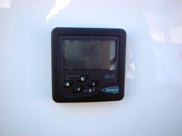 We
are installing a Horizon 150 series multi-display for the
knotmeter/depthsounder. This combines both functions in a single
unit. Installing the display could hardly be easier: determine the
location, drill a single hole with a holesaw (I think it was about 1-1/8")
and install the unit, using a supplied foam rubber gasket as a seal.
There's a plastic nut that just screws onto the protruding part of the back of
the instrument. Done. We
are installing a Horizon 150 series multi-display for the
knotmeter/depthsounder. This combines both functions in a single
unit. Installing the display could hardly be easier: determine the
location, drill a single hole with a holesaw (I think it was about 1-1/8")
and install the unit, using a supplied foam rubber gasket as a seal.
There's a plastic nut that just screws onto the protruding part of the back of
the instrument. Done.
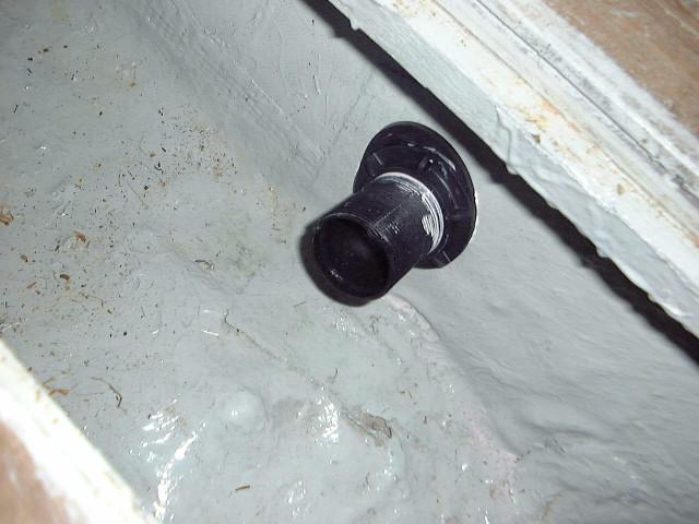
Installing the
two through hulls took several hours, all told, including the thought that went
into their eventual location. I went back and forth on the locations,
trying to come up with the best compromise of convenient interior location vs..
efficient exterior location. There were things in the way that prevented
locating the fittings where it might have been ideal. In the end, I
decided to mount the knotmeter just below the turn of the bilge in the keel, so
that the impeller is effectively vertical. I decided to mount the
depthsounder transducer on the starboard side near the vanity sink drain, just
aft of the main structural bulkhead (the one beneath the mast step). This
location seemed to offer the best compromise of accessibility from the inside
while retaining a spot outside that would be least affected by the keel shadow.
I drilled pilot
holes from the inside out in both locations, then went outside and drilled the
holes out with a 2" hole saw. I drilled the depthsounder hole more or
less vertically, which made for an oblong core sample. Then, I sanded the
bottom paint off the areas surrounding the two holes, so that the sealant would
have the best adhesion, and cleaned them with acetone.
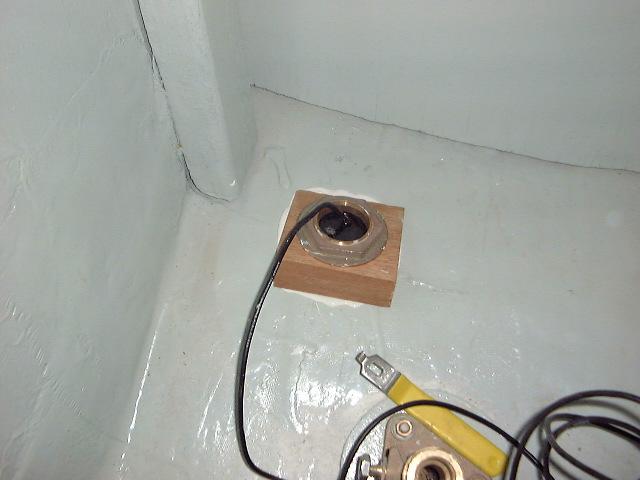
The depthsounder
needs to be mounted vertically for best performance, so I had to make a wooden
fairing block for the outside of the hull. Of course, the inside needs one
too to give the nut something to bear against. Making the block involved
estimating the deadrise of the hull with a bevel gauge, transferring the angle
to a piece of thick mahogany stock, and making the angled cut on a table
saw. Then, I drilled 2" holes through both pieces (for the through
hull) and test fit everything a few times, fine tuning as necessary.
|
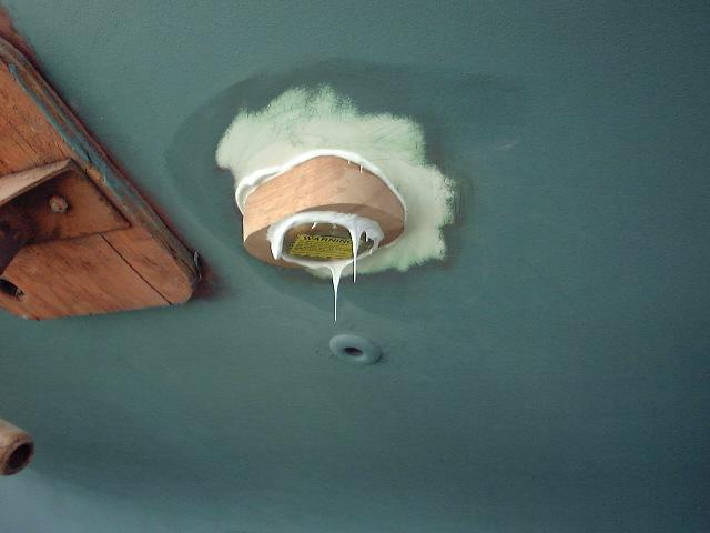
 Next,
I heavily gooped up the fittings with 5200 and pressed them into place. I
wasn't shy with the sealant, as I wanted a good seal. It always pays to
use way more than necessary, and clean up the excess later. I gooped the
fairing block too, as well as the threads on each fitting. Because of the
adhesive qualities of the 5200 and the tight holes, I was able to do this alone
without worrying about the fittings falling out. I went inside the boat Next,
I heavily gooped up the fittings with 5200 and pressed them into place. I
wasn't shy with the sealant, as I wanted a good seal. It always pays to
use way more than necessary, and clean up the excess later. I gooped the
fairing block too, as well as the threads on each fitting. Because of the
adhesive qualities of the 5200 and the tight holes, I was able to do this alone
without worrying about the fittings falling out. I went inside the boat  to
install the stop nuts on each fitting. The plastic knotmeter fitting comes
with a rubber interior gasket that helps accommodate the slight irregularities
of the hull; all I had to do was tighten it down hand tight, making sure that
the notch in the fitting was aligned fore and aft. The depthsounder is
bronze, and required an interior fairing block because of the angle. to
install the stop nuts on each fitting. The plastic knotmeter fitting comes
with a rubber interior gasket that helps accommodate the slight irregularities
of the hull; all I had to do was tighten it down hand tight, making sure that
the notch in the fitting was aligned fore and aft. The depthsounder is
bronze, and required an interior fairing block because of the angle. |
|
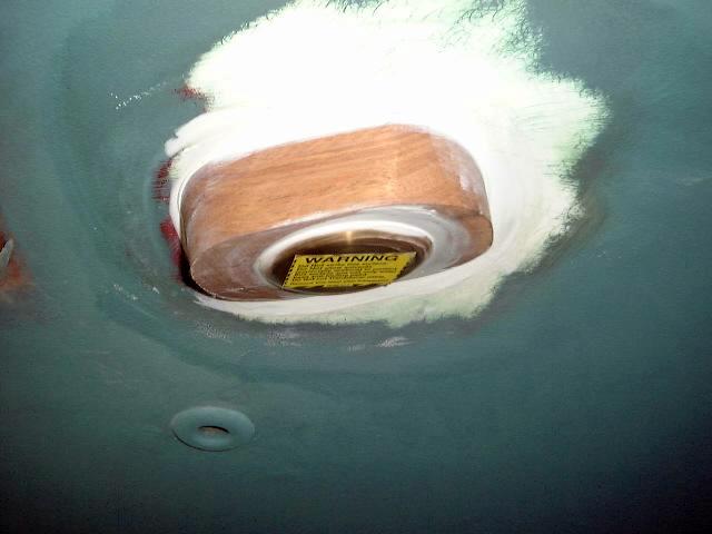
I spread a little 5200 on the hull beneath this block as well, pressed it into   place,
and threaded on the stop nut. There's just enough threads exposed to allow
about 1-2 full threads to pass beyond the nut when it was fully
tightened--barely made it! I tightened it hand-tight and went
outside again to check the positioning of the fairing block. Then, I used
channel locks to tighten it down as much as I could before the fitting began to
rotate. I went back outside and cleaned up the excess that had squeezed
out. place,
and threaded on the stop nut. There's just enough threads exposed to allow
about 1-2 full threads to pass beyond the nut when it was fully
tightened--barely made it! I tightened it hand-tight and went
outside again to check the positioning of the fairing block. Then, I used
channel locks to tighten it down as much as I could before the fitting began to
rotate. I went back outside and cleaned up the excess that had squeezed
out.
|
|
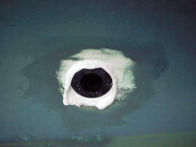
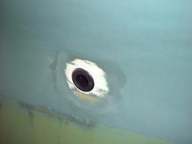
  Interior
of depthsounder and knotmeter fittings Interior
of depthsounder and knotmeter fittings
|
|
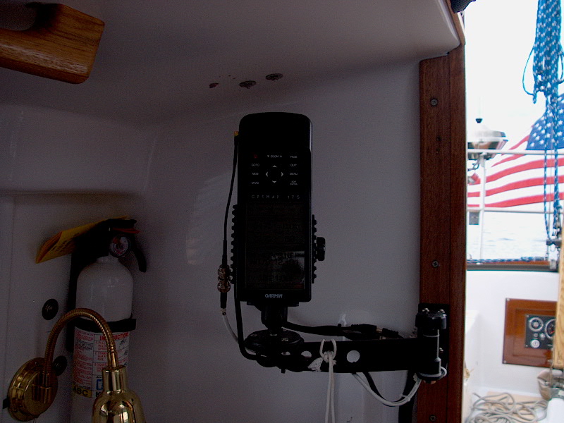
GPS
We have a Garmin GPSMAP 175, a
great unit with built-in plotter. It takes G-map cartridges. This is
a handheld unit, so we purchased the appropriate brackets, external antenna, and
power supply cable for semi-permanent installation. We also purchased a
swing-out mount that will mount inside the companionway, allowing the unit to be
read from the cockpit.
|
|
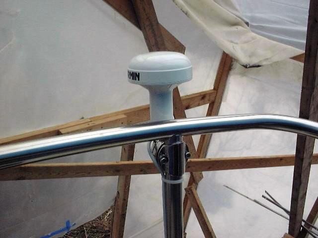
 installed the antenna on the stern pulpit. It screws into a standard
antenna bracket, which clamps onto the pulpit. I ran the wire down the
outside of one of the supports to deck level, then through a cable clam into the
lazarette. The cable clam actually looks like it will work; you
drill a hole through the deck and install the bottom piece, then drill a hole
the size of the cable through a rubber wedge. After slitting through the
wedge to
installed the antenna on the stern pulpit. It screws into a standard
antenna bracket, which clamps onto the pulpit. I ran the wire down the
outside of one of the supports to deck level, then through a cable clam into the
lazarette. The cable clam actually looks like it will work; you
drill a hole through the deck and install the bottom piece, then drill a hole
the size of the cable through a rubber wedge. After slitting through the
wedge to  one
side, you can slide the cable in. The whole thing is then wedged into
place with the top piece, squeezing the cable tightly in the rubber. I ran
the cable up to the cabin through the port cockpit locker, securing it along the
way as needed. one
side, you can slide the cable in. The whole thing is then wedged into
place with the top piece, squeezing the cable tightly in the rubber. I ran
the cable up to the cabin through the port cockpit locker, securing it along the
way as needed.
|
|
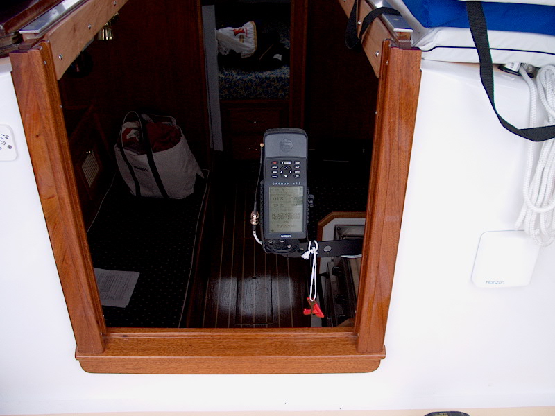
 To mount the unit, I purchased a
Garmin bracket for my particular unit, as well as a swing out bracket that I
mounted on the inside of the companionway. I also purchased the Garmin
power/data cable assembly. I installed the brackets as required, and ran
the power cable and antenna cable up to the units, keeping the cable run as neat
as possible, since it will be exposed. The bracket allows the GPS to be
swung out for cockpit To mount the unit, I purchased a
Garmin bracket for my particular unit, as well as a swing out bracket that I
mounted on the inside of the companionway. I also purchased the Garmin
power/data cable assembly. I installed the brackets as required, and ran
the power cable and antenna cable up to the units, keeping the cable run as neat
as possible, since it will be exposed. The bracket allows the GPS to be
swung out for cockpit  viewing, or left in the cabin for use there. It's a
pretty slick system; it makes the GPS very readable and usable from the cockpit,
which is really where you want it. The dodger protects the GPS from spray
and rain when in the out position. viewing, or left in the cabin for use there. It's a
pretty slick system; it makes the GPS very readable and usable from the cockpit,
which is really where you want it. The dodger protects the GPS from spray
and rain when in the out position.
|
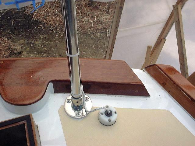
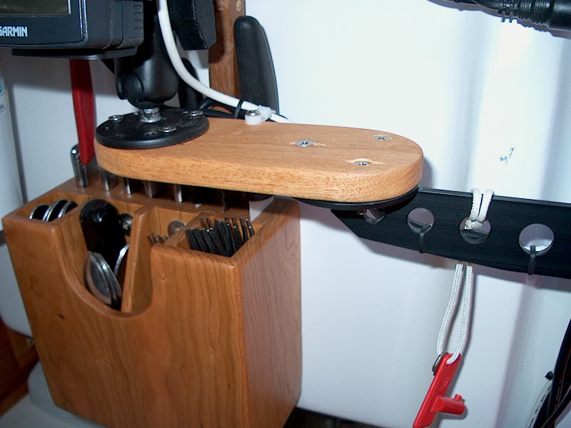
 I
had to slightly modify the GPS bracket and installation to accommodate my new
radar. This entailed moving the bracket to the bottom of the companionway
and adding a mahogany platform to extend the bracket's reach an extra 3" or
so to clear the radar display. See more about this here. I
had to slightly modify the GPS bracket and installation to accommodate my new
radar. This entailed moving the bracket to the bottom of the companionway
and adding a mahogany platform to extend the bracket's reach an extra 3" or
so to clear the radar display. See more about this here. |
|
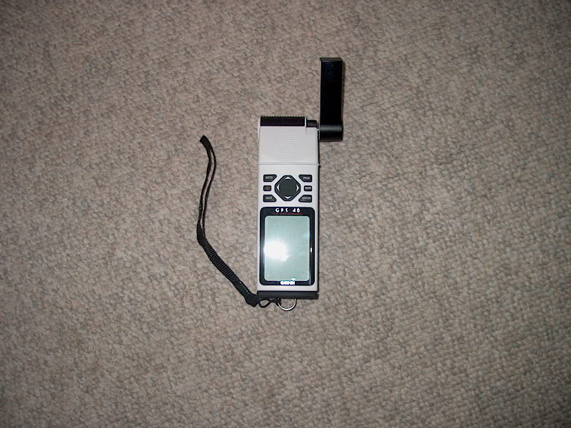
 Update!
For a backup, I purchased a nearly new Garmin GPS 48 handheld. These are
great little units, and I found one for a great price thanks to Ebay. I
wanted a backup in case something happened to our main unit, and also a small
one for travel, to take in the dinghy, and, God forbid, to keep in an abandon
ship bag. It's tiny--about 6" x 2"--and runs on AA
batteries. Update!
For a backup, I purchased a nearly new Garmin GPS 48 handheld. These are
great little units, and I found one for a great price thanks to Ebay. I
wanted a backup in case something happened to our main unit, and also a small
one for travel, to take in the dinghy, and, God forbid, to keep in an abandon
ship bag. It's tiny--about 6" x 2"--and runs on AA
batteries.
|
|
VHF
 The VHF is a West Marine Aurora. It's pretty basic, but we don't need it for much more
than calling the launch at the end of the day. We also have a couple
handheld radios. During wiring operations, I ran the power supply from the
panel to the VHF location--on the port side above the icebox. I also ran a
length of coax up to the mast area, leaving extra for the final run through a
waterproof fitting in the deck. I will run another length through the mast
to a new antenna. The VHF is a West Marine Aurora. It's pretty basic, but we don't need it for much more
than calling the launch at the end of the day. We also have a couple
handheld radios. During wiring operations, I ran the power supply from the
panel to the VHF location--on the port side above the icebox. I also ran a
length of coax up to the mast area, leaving extra for the final run through a
waterproof fitting in the deck. I will run another length through the mast
to a new antenna.
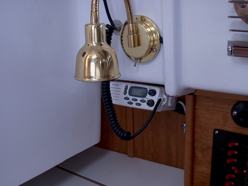
I installed the VHF next to the
electrical panel, above the icebox. With the mast stepped, I made up the
antenna cable connections using Shakespeare center pin PL-259 connectors, which
seem to work well. The power cables for the VHF run behind the trim panel
to the electrical panel next door.
Update!
In addition to the fixed mount VHF, we have three handhelds. I have an
older ICOM IC-M5 (on the right in the photo below) that is a great, rugged
radio, but the battery doesn't contact properly and it doesn't always
work. Usually, fiddling with it and removing and reinstalling the battery
gets it to turn on, but it's unreliable for general use. It makes a good
backup, though, or one to bring up to the vee berth at night so I can listen to
the weather reports.
|
|
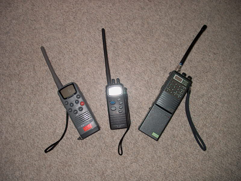 To
supplement the old ICOM, I bought a Horizon HX150S (on the left in the photo to
the left) a couple years ago. It worked fine until this year, when for
some reason it seemed to stop working properly. I couldn't get weather on
it, and it didn't seem to transmit (or maybe it just doesn't receive.
Perhaps it's a battery issue--I may get a new battery pack for it.
Supposedly, the radio can operate on standard AA batteries, but they don't just
slip in in place of the standard battery pack--I've never really tried.
Anyway, I was disgusted with this radio this past season, and decided to look
for a good replacement. Naturally, as I tend to do now--a recent
infatuation--I turned to Ebay. To
supplement the old ICOM, I bought a Horizon HX150S (on the left in the photo to
the left) a couple years ago. It worked fine until this year, when for
some reason it seemed to stop working properly. I couldn't get weather on
it, and it didn't seem to transmit (or maybe it just doesn't receive.
Perhaps it's a battery issue--I may get a new battery pack for it.
Supposedly, the radio can operate on standard AA batteries, but they don't just
slip in in place of the standard battery pack--I've never really tried.
Anyway, I was disgusted with this radio this past season, and decided to look
for a good replacement. Naturally, as I tend to do now--a recent
infatuation--I turned to Ebay.
I found a nice new ICOM IC-M1 (in
the middle), and won it for less than half of its list price. It's very
nice--just got it. I really like it, although I haven't really used it or
anything. But it's a nice size, and is high quality as well.
|
|
|
|
Please
click here to continue. |
|