|
The Galley Sink Drain
This page was last updated on 22 March 2003
During the first two seasons of
use since the restoration, the galley sink continued to plague us with
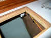
annoyances. The original sink I installed, a wonderful, 9" deep
version, was way too deep for the location in the galley--the bottom of the sink
was lower than the waterline outside, so the sink always contained several
inches of water. On to plan B: install a shallower (5")
sink. This worked OK during the first season with the boat, though the
water level was still barely below the bottom of the sink. When we loaded
the boat heavily the second season with more cruising gear and provisions, water
tended to enter the sink, especially when people were sitting in the
cockpit. Also, when sailing on port tack if the sink drain was open, water
would come in alarmingly.
After dealing with this
annoyance, and potential hazard to the safety of the boat, I decided to take the
drastic measure of installing a sump chamber and pump in order to better handle
the sink drain. Electric pumps tend to be power hungry and prone to
failure, but I didn't see any true choice in this case. Plus, installing
this rig would allow a seacock to be permanently closed and sealed--always a
good thing.
|
 The
first step was to remove the old drain assembly and hose. In the
tight confines of the space beneath the sink, this proved to be fairly
difficult, and ended up sawing through the metal tailpiece on the sink
to get that end of the hose free. Once that was done, I could
twist it off the seacock tailpiece more easily. Then, I had to cut
the drain off the sink too, since the cheap metal tailpiece and its nut
had corroded together from all that salt water. Again, the
relatively tight access (but at least I do have clear access!!) made
this a bit tougher than it could have been, but I got it done. The
first step was to remove the old drain assembly and hose. In the
tight confines of the space beneath the sink, this proved to be fairly
difficult, and ended up sawing through the metal tailpiece on the sink
to get that end of the hose free. Once that was done, I could
twist it off the seacock tailpiece more easily. Then, I had to cut
the drain off the sink too, since the cheap metal tailpiece and its nut
had corroded together from all that salt water. Again, the
relatively tight access (but at least I do have clear access!!) made
this a bit tougher than it could have been, but I got it done.
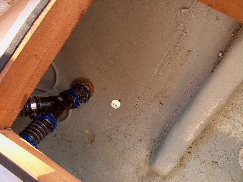
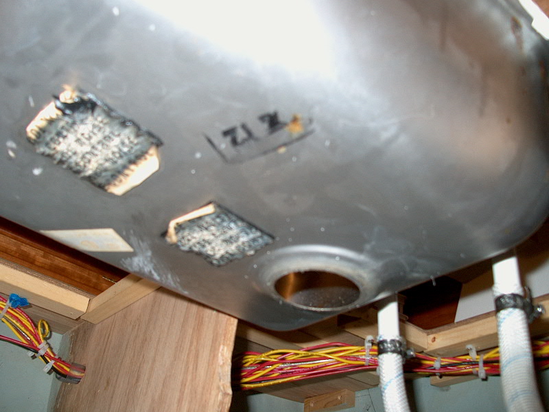
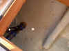
With
the old drain out of the way, the first order of business was to seal
off the now-unnecessary seacock. I removed the tailpiece and
replaced it with a bronze plug, and shut the seacock. Should I
ever need it again, it will be usable, and I don't intend to remove the
fitting itself--a blanked-off seacock is as good as no seacock at all,
especially when the through hull and seacock are only two years old to
begin with.
|
 I
assembled the various pieces and parts I needed to complete this
job. Earlier, I had purchased an Attwood shower sump system, which
consists of a bilge pump and float switch mounted in a sealed plastic
container with a variety of hose nipples on one end for intake and
discharge. The directions call for the discharge (overboard) hose
to run continually upwards from the sump to prevent airlock or water
remaining in the chamber, but should this be impossible, there's a
provision for drilling a vent hole in the clear plastic cover. I
spent quite a bit of time considering my various options for where to
pump this thing overboard. The easiest thing would be to install a
through hull fitting in the topsides just opposite where the pump is
located, which would end up being a bit aft of amidships on the
starboard side (where the galley is). However, I didn't really
want to install a fitting here, for several reasons. First and
foremost, this location would surely lead to an unsightly streak of gunk
on the side of the hull, a combination of bronze residue, soap scum, and
food bits from the sink. Yuck--and totally unacceptable to
me. I certainly wouldn't consider locating the discharge anywhere
but at the gunwale, because nearer the waterline would guarantee that it
would frequently be below the heeled waterline, and would allow back flooding. I
assembled the various pieces and parts I needed to complete this
job. Earlier, I had purchased an Attwood shower sump system, which
consists of a bilge pump and float switch mounted in a sealed plastic
container with a variety of hose nipples on one end for intake and
discharge. The directions call for the discharge (overboard) hose
to run continually upwards from the sump to prevent airlock or water
remaining in the chamber, but should this be impossible, there's a
provision for drilling a vent hole in the clear plastic cover. I
spent quite a bit of time considering my various options for where to
pump this thing overboard. The easiest thing would be to install a
through hull fitting in the topsides just opposite where the pump is
located, which would end up being a bit aft of amidships on the
starboard side (where the galley is). However, I didn't really
want to install a fitting here, for several reasons. First and
foremost, this location would surely lead to an unsightly streak of gunk
on the side of the hull, a combination of bronze residue, soap scum, and
food bits from the sink. Yuck--and totally unacceptable to
me. I certainly wouldn't consider locating the discharge anywhere
but at the gunwale, because nearer the waterline would guarantee that it
would frequently be below the heeled waterline, and would allow back flooding.
|
|
All considerations seemed to point to
mounting the discharge well aft, probably in the counter where it would
be out of sight and any residue from the fitting would not be
particularly visible. However, mounting the discharge there would
mean a much longer hose run, and the impossibility of keeping the whole
line running continually upwards (at least not easily). And the
location in the counter could still conceivably allow back siphoning
into the pump under certain conditions. On balance, though, this
seemed to be the best location, so I bought enough hose to r each all
the way there from the galley. I also purchased a threaded bronze
through hull fitting (3/4"), a bronze shutoff valve, and a bronze
90° tailpiece fitting (all for 3/4" hose). To complete the
sump installation, I also purchased some duplex wire and a switch to isolate
the pump and shut if off if desired. I had to order a new sink
drain fitting to replace the one I cut off earlier, since I couldn't
source one locally.
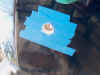 With
all the pieces on hand, I chose a nice, very warm afternoon (finally!)
to install the through hull fitting. After hemming and hawing for
some time, and looking at the hull in a few places from both inside and
outside, I chose the location in the starboard counter near the existing
bilge pump outlet, and, from the inside, drilled a small pilothole to
the outside. After confirming the location, I applied some masking
tape over the hull on the outside to help control chipping; then, still
outside the hull, I cut a 1" hole with a hole saw (the correct size
to fit the threaded through hull fitting). One more hull core
sample to add to my collection! With
all the pieces on hand, I chose a nice, very warm afternoon (finally!)
to install the through hull fitting. After hemming and hawing for
some time, and looking at the hull in a few places from both inside and
outside, I chose the location in the starboard counter near the existing
bilge pump outlet, and, from the inside, drilled a small pilothole to
the outside. After confirming the location, I applied some masking
tape over the hull on the outside to help control chipping; then, still
outside the hull, I cut a 1" hole with a hole saw (the correct size
to fit the threaded through hull fitting). One more hull core
sample to add to my collection!
 After
removing the tape, I tried the fit of the through hull--the hole was a
bit snug, so I reamed it out a small amount with a drum sander
attachment on my drill. Once the fit was right, I cleaned the
inside of the hole, the hull, and the inside of the hull with some paint
thinner to remove dust and contaminants. After
removing the tape, I tried the fit of the through hull--the hole was a
bit snug, so I reamed it out a small amount with a drum sander
attachment on my drill. Once the fit was right, I cleaned the
inside of the hole, the hull, and the inside of the hull with some paint
thinner to remove dust and contaminants.
Next, I preassembled the
bronze shutoff (ball) valve with the 90° bronze tailpiece. I
applied some Teflon tape to the threads and tightened the two pieces
together, ensuring that the nipple faced the way I wanted it to when it
was tight. I took the time to do this step ahead of time so that I
could ensure that the assembly would be properly aligned when I
installed the valve on the threaded through hull fitting. Because
this fitting is above the waterline, I saw no need for a flanged,
through-bolted seacock, but wanted a solid shutoff valve so that I can
close this fitting off should there be following seas or other
conditions that threaten to back siphon into the sump through the
counter. For most conditions we expect to experience, this should
not be an issue.
|
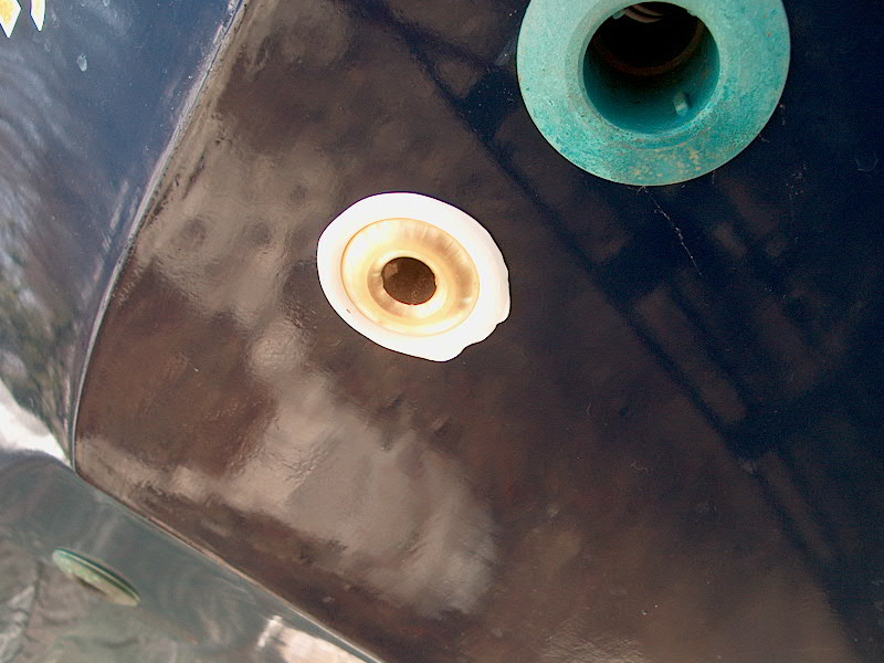
 With
both sides cleaned up, I heavily gooped up the through hull flange with
polysulfide caulk, and applied some to the first inch or so of the
threads as well. Then, I inserted the fitting into the hull from
the outside; the fit was tight enough that it stayed by itself while I
went aboard to install the nut. On the inside, I applied a bit
more caulk around the fitting, then screwed the nut down tightly, first
by hand and then with a wrench. I inserted a bar into the fitting
from the inside to hold the mushroom from turning while I tightened the
nut. With
both sides cleaned up, I heavily gooped up the through hull flange with
polysulfide caulk, and applied some to the first inch or so of the
threads as well. Then, I inserted the fitting into the hull from
the outside; the fit was tight enough that it stayed by itself while I
went aboard to install the nut. On the inside, I applied a bit
more caulk around the fitting, then screwed the nut down tightly, first
by hand and then with a wrench. I inserted a bar into the fitting
from the inside to hold the mushroom from turning while I tightened the
nut.
|
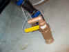 When
the nut was tight, I cleaned off the excess caulk that squeezed out
around the nut, and screwed the ball valve assembly onto the remaining
threads. The nut below held the through hull tight enough to
prevent it from turning when I tightened the valve in place. I did
twist the whole assembly just enough when it was tight to align the
valve handle and 90° nipple the correct direction. When
the nut was tight, I cleaned off the excess caulk that squeezed out
around the nut, and screwed the ball valve assembly onto the remaining
threads. The nut below held the through hull tight enough to
prevent it from turning when I tightened the valve in place. I did
twist the whole assembly just enough when it was tight to align the
valve handle and 90° nipple the correct direction.
|
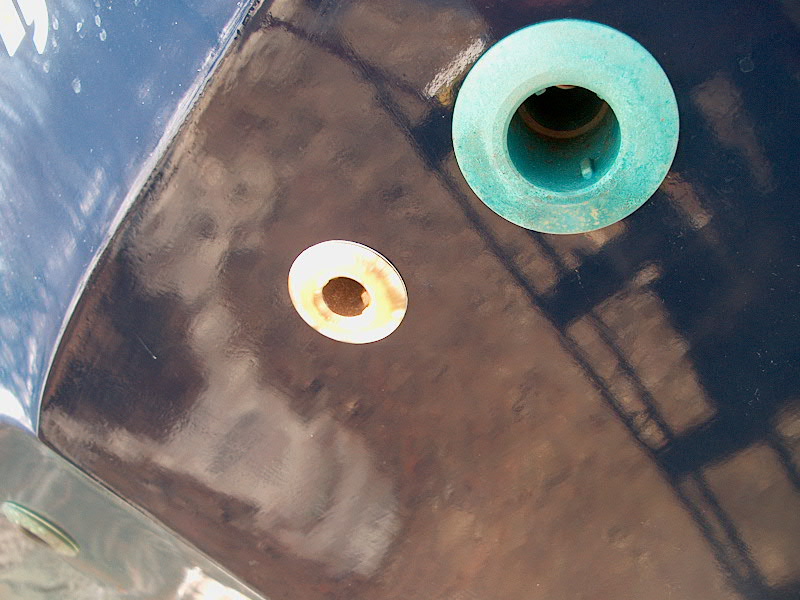
 Next,
I went back outside and down to the ground, and cleaned up the caulk
squeezeout around the mushroom fitting. Next,
I went back outside and down to the ground, and cleaned up the caulk
squeezeout around the mushroom fitting.
|
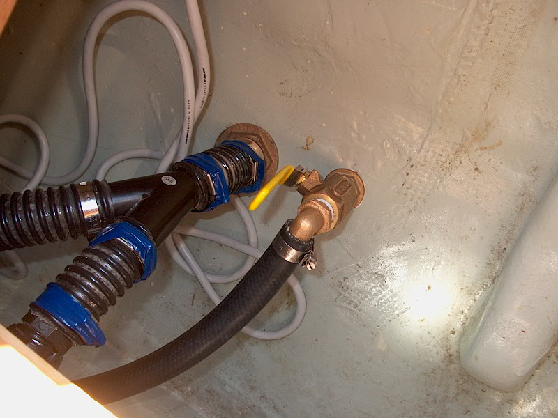
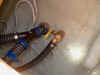 With
the fitting all installed and cleaned up and secure, I ran a length of
3/4" black fabric-reinforced hose from the lazarette to the galley,
following the path used by the bilge pump hoses. I secured the end
of the hose to the new valve and nipple with an AWAB clamp, and
routed the hose into the locker beneath the galley where I planned to
locate the new sump pump. I let the other end run wild for now,
and secured the hose with plastic cable ties in several places along its
run. With
the fitting all installed and cleaned up and secure, I ran a length of
3/4" black fabric-reinforced hose from the lazarette to the galley,
following the path used by the bilge pump hoses. I secured the end
of the hose to the new valve and nipple with an AWAB clamp, and
routed the hose into the locker beneath the galley where I planned to
locate the new sump pump. I let the other end run wild for now,
and secured the hose with plastic cable ties in several places along its
run.
|
|
 I ran a
length of 14/2
sheathed safety cable (red and yellow wires) from the positive and
negative distribution busses behind the electrical panel over to the
galley. At the positive distribution end, I installed a 4-amp
inline fuse, as called for in the pump wiring directions.
Following preexisting wiring runs, I threaded the cable along until I
reached the galley locker where the pump was to be installed, securing
it every so often with plastic wire ties. Inside the locker,
where it would be convenient if needed, I installed a rocker switch to
allow the power to be shot off to the automatic pump. It should be
on most or all of the time, but the switch is a good idea just in case. I ran a
length of 14/2
sheathed safety cable (red and yellow wires) from the positive and
negative distribution busses behind the electrical panel over to the
galley. At the positive distribution end, I installed a 4-amp
inline fuse, as called for in the pump wiring directions.
Following preexisting wiring runs, I threaded the cable along until I
reached the galley locker where the pump was to be installed, securing
it every so often with plastic wire ties. Inside the locker,
where it would be convenient if needed, I installed a rocker switch to
allow the power to be shot off to the automatic pump. It should be
on most or all of the time, but the switch is a good idea just in case.
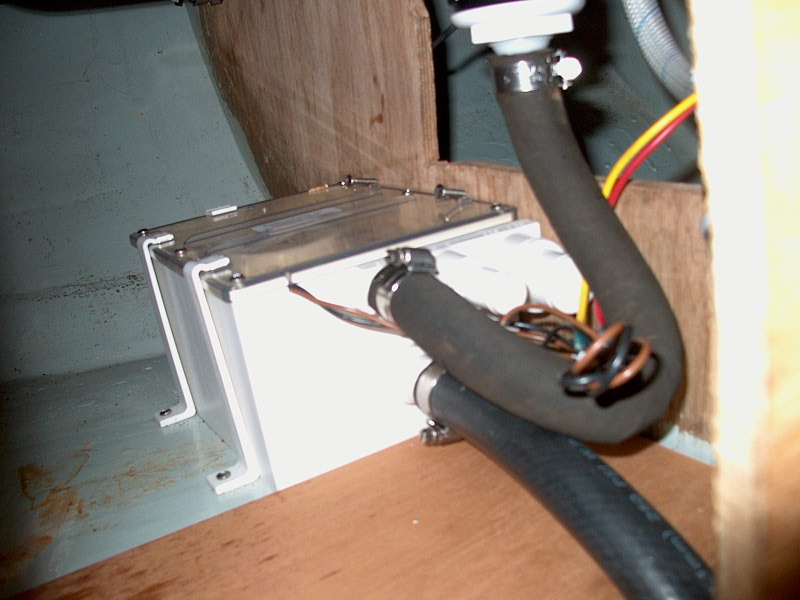
Next, it was time for the
final sump installation, wiring, and plumbing connections. First,
I secured the plastic top of the sump with six screws, drilling through
the top into the provided screwholes along the edges. With the top
now secured in place, it was time to install the sump chamber in place
in the locker beneath the sink. I decided to install it tightly
against the rear bulkhead, partly because it was the best location, but
also for the sake of convenience; with access to this locker as
difficult as it was, and requiring various contortions on my part,
installing the sump where I did meant that I only needed to install two
of the four hold down clamps to secure the chamber in place. Fewer
fasteners to install whilst standing on one's head is a happy
thing. I secured the chamber with two hold down clamps on one
side, and I drove two longish screws into the rear bulkhead just above
the top of the sump to effectively hold that side down. Since I
had spare clamps, I installed one at the far end just in case the
chamber showed any inclination to slide athwartships.
 With
the sump now secured in place, I completed the wiring, leaving plenty of
extra wire bundled up nearby so that I can pull the sump up on top of
the counter for maintenance without undoing the wiring, should such
maintenance become necessary. Finally, I installed the new sink
drain to replace the one that I was forced to cut earlier in the process,
and connected the discharge hose to the appropriate nipple on the
sump. The fabric-reinforced hose proved to lack the stiffness
needed to make the tight bend between the sink drain and the sump
intake, so I rummaged around in the shop and found a length of
wire-reinforced hardwall hose left over from something else, and
installed that from the sink to the sump. With
the sump now secured in place, I completed the wiring, leaving plenty of
extra wire bundled up nearby so that I can pull the sump up on top of
the counter for maintenance without undoing the wiring, should such
maintenance become necessary. Finally, I installed the new sink
drain to replace the one that I was forced to cut earlier in the process,
and connected the discharge hose to the appropriate nipple on the
sump. The fabric-reinforced hose proved to lack the stiffness
needed to make the tight bend between the sink drain and the sump
intake, so I rummaged around in the shop and found a length of
wire-reinforced hardwall hose left over from something else, and
installed that from the sink to the sump.
Project
complete. |
Update: 2008
After dealing with a variety of ultimately unsuitable modifications to
the galley sink setup, I decided to completely reconfigure the system,
reverting to a deep sink and locating a new sump chamber in the bilge,
far removed from the sink itself so as to address several issues with
the "third try's a charm" semi-original setup that I installed in 2003.../maintenance/maintenancelog2009.html#71809
Read more about the newest changes in the
winter
2008 refit log.
Update: July 2009
The sealed automatic switch (non-Mercury, non-float) that came with
the Johnson sump chamber failed to work acceptably or even marginally,
forcing me to replace it with an older, spare mercury float switch left
over from my previous installation. Read more about the fix
here.
|
|