|
The Ever-Settling Waterline (Page 2)
This page was last updated on 7
October 2002.
Setup
and Striking a
Level Waterline
One of the things
I determined during the summer was that the top boottop scribe mark was not
level and parallel to the water's surface, but in fact incorporated a fairly
significant sheer. This is appropriate, attractive and proper for the upper
edge of a boottop, and I will provide some sheer for my new boottop when the
time comes, but I feel that the bottom edge of the boottop--which in this case
corresponds with the top of the antifouling paint--should be dead straight and,
most importantly, parallel with the surface of the water.
First, though,
here's a basic summary of the status of the various lines on the boat, incase it
becomes less clear later.
-
The BOTTOM
SCRIBE mark (what one might term the original Designed WaterLine, or
DWL) is straight and planar.
-
The UPPER
SCRIBE mark (the upper edge of the original boottop, and the
point to which I raised the antifouling paint when I repainted the hull) is
NOT straight and planar; rather, it incorporates a curve, or sheer, which is
proper for an upper boottop edge, but not for the waterline. This
upper scribe mark is also the bottom edge of my current boottop; the fact
that it is not planar leads in large part to the strange waterline we had
when the boat was fully loaded this season.
-
The TOP OF
MY CURRENT BOOTTOP is also curved, or sheered.
-
Finally, what
I am trying to accomplish is to have the new waterline (edge of the bottom
paint) parallel to the water, and straight and planar--and more reflective
of where the boat actually floats. This will give the new boottop a
straight lower edge also, and I will curve, or sheer, the top edge for an
attractive look.
My first step
towards a new, straighter, and higher waterline and boottop was to confirm my
on-water observations of the unlevelness of the current paint job. To do
this, as well as strike a new level line higher up, I needed to establish a
level line that simulates the surface of the water. There are a few ways
that this could be done, one of which is with a transit and/or laser
level. These are effective methods of going about this, but require that
the boat be leveled not only side to side, but also end for end for best
accuracy. Plus, you need to have a transit on hand--I don't.
Additionally, I
wanted a true visual representation of what was going on, so I really wanted to reproduce
the ocean surface in my backyard to confirm my thoughts and ensure that the new
striping would end up the way I wanted. Therefore, I chose a different
method. This method, adapted from one described in Details of Classic
Boat Construction: The Hull, by Larry Pardey, is simple and effective,
provides a true visual planar reference to help with the process, and I could
easily accomplish it with materials on hand.
My first step was
to level the boat side to side. It was pretty close, but I had to adjust
the stands a bit to get it nearly perfect. Fore and aft leveling is not
important for this method, as you will see in the description as we continue.
|
|
|

|
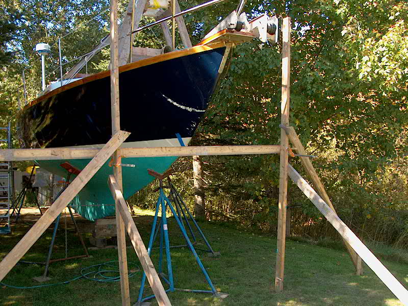
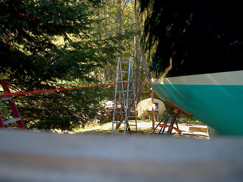
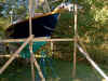
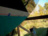
Using some old 2x4s left
over from my construction shed, I erected a structure at each end of the
boat, consisting of two vertical supports (one on each side), bracing to
hold the verticals in position, and a horizontal beam spanning between
the two vertical members. To secure the various pieces to the
ground, I drove stakes into the dirt, after cutting points on the end of
the stakes, and screwed the various supports to the stakes. |
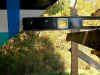 |
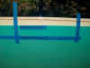
Next, I leveled the
horizontal beam side to side, and positioned it so that the top edge was
at the exact same height as the current waterline, which on my boat is
located at the top scribe mark of the original boottop from the
factory. Because the beams are located a short distance away from
the hull at each end, I used a short level and a metal ruler extension
to transfer the level of the beam back to the hull at each end. I
began with the original waterline because I wanted to confirm my
impressions about the waterline sheer before I began the process of
striking a higher line. |
 |
 |
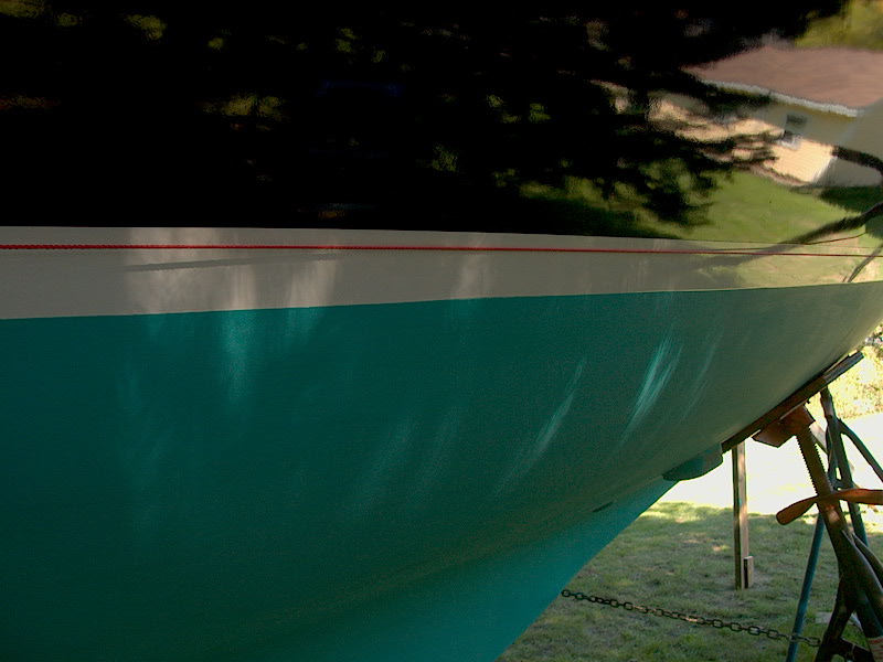
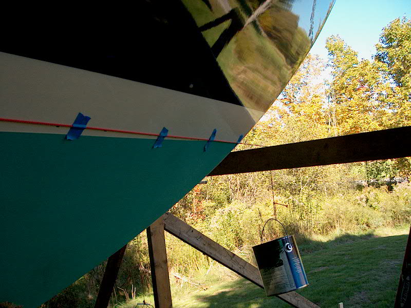
Once I had the beams
leveled at the right height, I ran strings fore and aft on each side,
hanging weight (in my case, paint cans) from each end to hold the
strings in place and taut between the forward and after beams.
Then, I adjusted each string inward until it touched the hull at its
widest point, and at the same point on each side of the boat. |
 |
|
 |
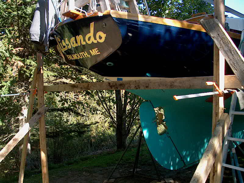
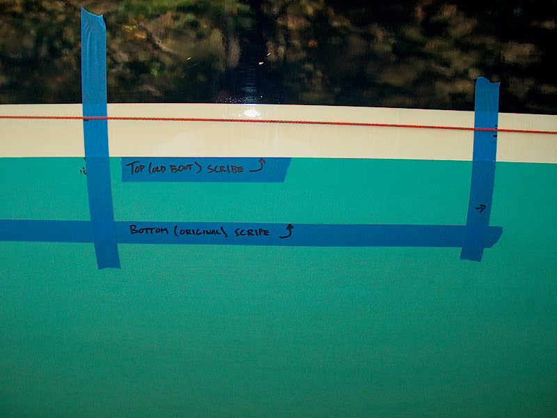
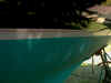
These photos show the
position of the string amidships on each side of the boat at the
original waterline height, bow and stern. Note in the righthand
photo the notations showing the levels of the two scribe marks and their
locations relative to the string, which represents the actual loaded
waterline. (Yes, the boat is heavy!) Remember, the string is
right at the top scribe mark at the bow and stern, which shows the
amount of sheer in the top scribe mark. |
 |
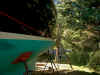
With the string touching
the hull at its widest point on each side, I began the process of transferring
the straight, level line to the hull from the string. This is a
test run only, as I will be raising the level by an inch or two in the
final stage, but I wanted to go through the process. To transfer
the line from the string to the hull, I started by securing the string
to the hull where it touched with some tape, then marked on the hull
with a sharpie. Then, I moved each end of the string inboard (by
sliding the weighted string along the horizontal beams at each end of
the boat) until it touched the hull again 4" - 6" further
along from the previous point, then taped the string again and marked
the line. The taping (or otherwise securing) the string to the
hull is required to prevent the string from slipping up or down the
curvature of the hull as it tightens. This ensures that the line
remains level and straight as it is moved in. I repeated this
process towards the bow and stern until I had the whole line marked on
the hull. In the extreme aft portions beneath the counter, where
the hull is highly curved and hollow, I transferred the string level to
the hull with a level held between the string and the hull. |
 |
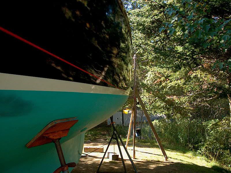
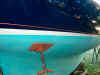
You can see how the
string begins at the intersection of the boottop and antifouling paint
at the stem and quickly extends into the white boottop. This is a
straight line running to the same intersection at the centerline in the
stern. |
 |
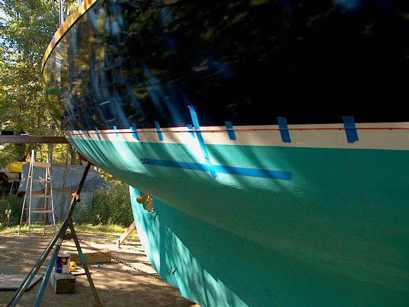
With
the string tight along the hull the entire length, I now had marks
indicating the level line between the bow and stern, so I could remove
the string and eye my line for fairness and accuracy. The black
pen marks on the boottop are the result of this exercise; I didn't worry
about putting the marks on the hull since this area will be sanded and
repainted when all is said and done anyway. Remember: those
black marks indicate a perfectly straight line between the stem and
stern at the centerline. Although it looks like my new line curves
upwards amidships, this is simply an optical illusion caused by the fact
that the old boottop and bottom actually dip down, or sag, amidships,
the result of the sheer, or curve, of the top scribe
mark. |
|
|
The process as described above,
including second guessing, remeasuring, and double checking, took me between
three and four hours on a beautiful fall afternoon to complete. I
proceeded very methodically to ensure that I didn't make a mistake.
With my trial run complete,
confirming the existing waterline, I moved on towards raising the line by
1" - 2"...I haven't decided yet. Since this is the loaded
waterline, I might only raise it one inch so that it doesn't appear to float way
too high when the boat is less heavily loaded. This is still under
evaluation. Before I quit for the day, I did raise the horizontal beams at
each end of the boat, first to 2" above the existing line, which seemed
ridiculously high, so I lowered it to 1" above the existing line, which
seemed to be about right.
Please
click here to continue.
|
|