|
Schaefer 1100
Roller Furling System
This page was last updated on 30 January 2002
Last fall, we purchased the roller furling
system to take advantage of 2000 pricing and a good deal from our local
sailmaker. With spring in the air, and the sailmaker hankering for a hoist
measurement so they could build out new genoa, it was time to assemble the
system, at least partially.
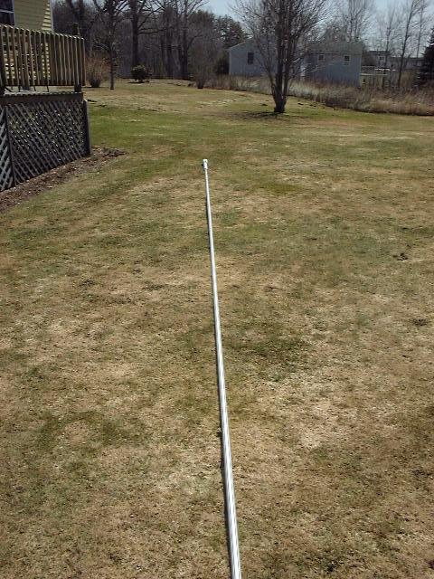
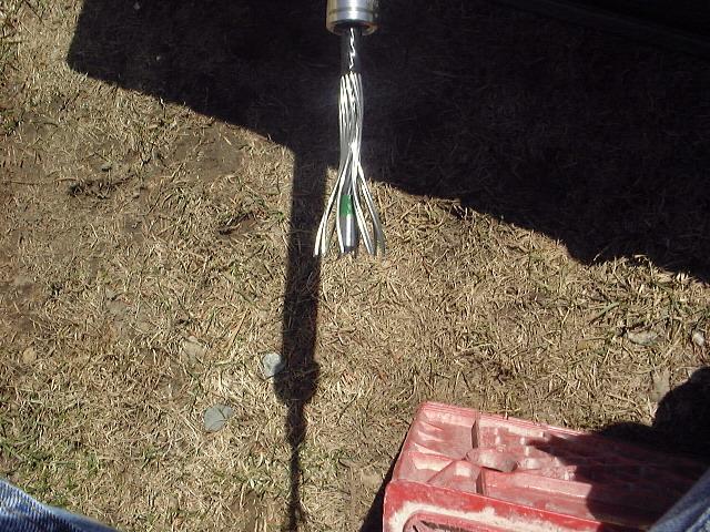
 The
first step was to obtain a new headstay, which I purchased from my rigger.
He installed a swaged terminal at the lower end, but left the top end raw to
accept a Stalok terminal that is part of the roller furling kit. We had
measured the old headstay that came with the boat, but I wanted to double check
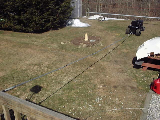
before cutting the new one to the proper size. To do this, I stretched it
out in the back yard by tying one end to the deck and using my tractor to
pull it taut. Then, I was able to get an accurate measurement. I
also disassembled part of the old decrepit roller furler that was installed so I
could determine whether the turnbuckle was open or closed. (open).
The measurement, pin to pin with the turnbuckle open, was 31'-8-1/2".
I made some subtractions to the length to account for parts of the roller
furling system--the lower link plate, the Stalok terminal, and a double toggle
at the upper end. This made for a total deduction of 8-3/8", so I cut
my new headstay (turnbuckle open) to 31'-0-1/8". The
first step was to obtain a new headstay, which I purchased from my rigger.
He installed a swaged terminal at the lower end, but left the top end raw to
accept a Stalok terminal that is part of the roller furling kit. We had
measured the old headstay that came with the boat, but I wanted to double check
before cutting the new one to the proper size. To do this, I stretched it
out in the back yard by tying one end to the deck and using my tractor to
pull it taut. Then, I was able to get an accurate measurement. I
also disassembled part of the old decrepit roller furler that was installed so I
could determine whether the turnbuckle was open or closed. (open).
The measurement, pin to pin with the turnbuckle open, was 31'-8-1/2".
I made some subtractions to the length to account for parts of the roller
furling system--the lower link plate, the Stalok terminal, and a double toggle
at the upper end. This made for a total deduction of 8-3/8", so I cut
my new headstay (turnbuckle open) to 31'-0-1/8".
|
|
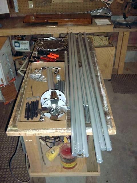
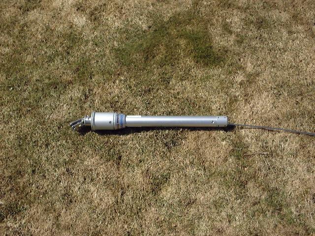
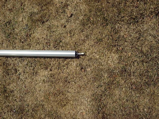
  I
laid out all the parts that came with my furling system. This included a
number of aluminum foils, the drum assembly,
connectors, rivets, and a few other pieces. With everything organized, I
was ready to begin. The first thing to do was to disassemble the drum
assembly, so I did that according to the instructions. I
laid out all the parts that came with my furling system. This included a
number of aluminum foils, the drum assembly,
connectors, rivets, and a few other pieces. With everything organized, I
was ready to begin. The first thing to do was to disassemble the drum
assembly, so I did that according to the instructions.
|
 Next,
I installed the short link plate at the bottom of the headstay, and closed the turnbuckle
as required. Then, I slid the lower swivel over the top of the stay and
down to the bottom, securing it with a pin. Next,
I installed the short link plate at the bottom of the headstay, and closed the turnbuckle
as required. Then, I slid the lower swivel over the top of the stay and
down to the bottom, securing it with a pin.
|
|
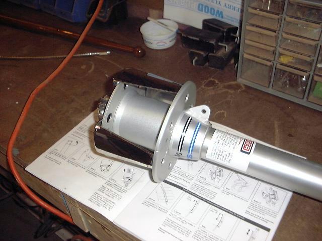
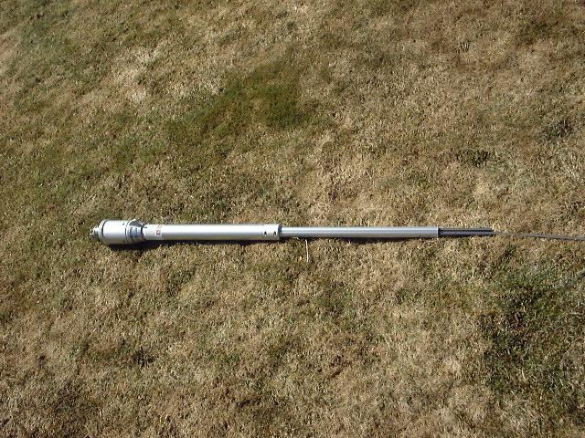
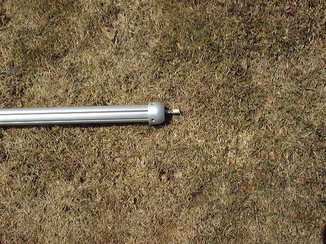
 I
slid the torque tube assembly over the stay, and secured it to the lower swivel
as required. This tube is where the turnbuckle resides, and it is
relatively easily disassembled for easy turnbuckle adjustment. I
slid the torque tube assembly over the stay, and secured it to the lower swivel
as required. This tube is where the turnbuckle resides, and it is
relatively easily disassembled for easy turnbuckle adjustment.
|
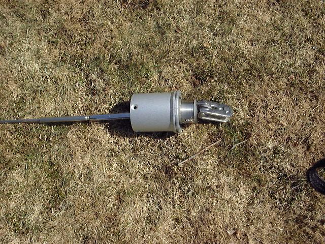
 Next,
I slid down the first, special section of foil extrusion, which is designed to
slip into the torque tube and is then clamped in place with a special fitting. Next,
I slid down the first, special section of foil extrusion, which is designed to
slip into the torque tube and is then clamped in place with a special fitting. |
|
 The
next part was the stainless steel feeder, which attached directly to the
lowermost section. The
next part was the stainless steel feeder, which attached directly to the
lowermost section.
|
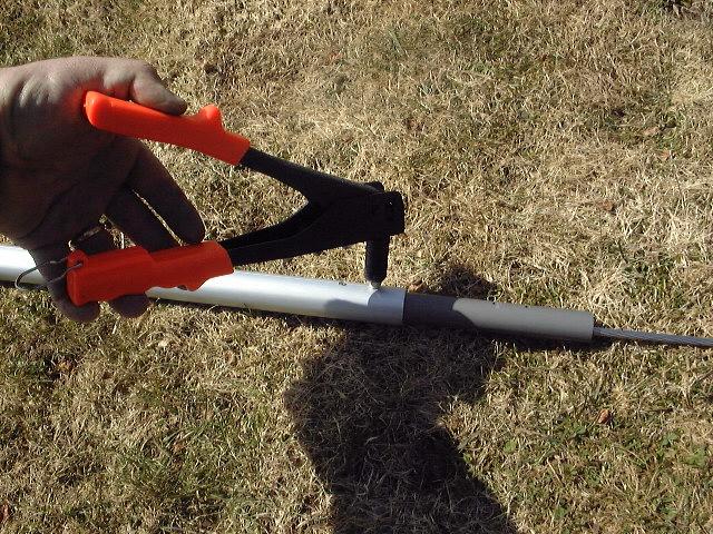
 With
the feeder installed, I began slipping full extrusions over the stay, and
connecting them with special connector pieces that come with the kit. Each
joint is then secured with eight rivets--four in each end. I continued
installing the extrusions in this way until I was about 8' from the top of the
stay. With
the feeder installed, I began slipping full extrusions over the stay, and
connecting them with special connector pieces that come with the kit. Each
joint is then secured with eight rivets--four in each end. I continued
installing the extrusions in this way until I was about 8' from the top of the
stay. |
 Near
the top of the stay, I had to cut the last extrusion to length.
Laying the last two pieces out, I determined the final length as called for in
the instructions and cut the extrusion with a hacksaw. Then, I installed
it in the same way. This leaves a couple inches of the stay exposed at the
top. I then slid the upper swivel assembly over the top and down the stay. Near
the top of the stay, I had to cut the last extrusion to length.
Laying the last two pieces out, I determined the final length as called for in
the instructions and cut the extrusion with a hacksaw. Then, I installed
it in the same way. This leaves a couple inches of the stay exposed at the
top. I then slid the upper swivel assembly over the top and down the stay. |
|
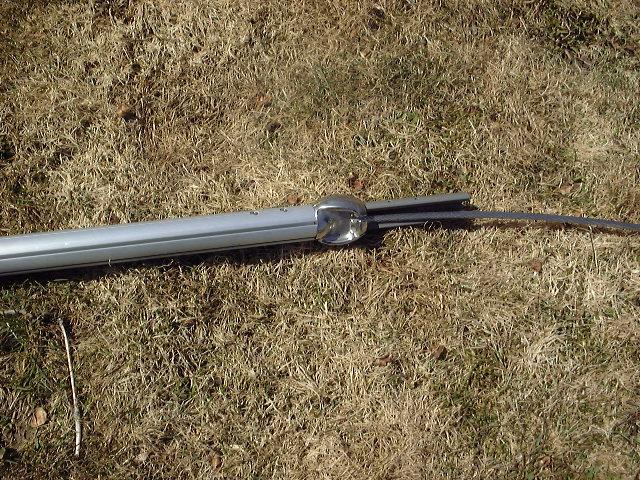
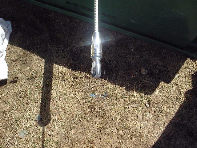
 The
top of the stay is then secured with a special joint connector, and covered with
an aluminum cap. The
top of the stay is then secured with a special joint connector, and covered with
an aluminum cap.
|
|
 Here
is the completed foil assembly. Here
is the completed foil assembly.
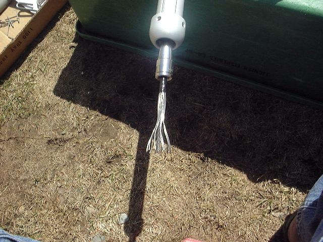
With the foil installed, it was time to
install the Norseman terminal at the top. I had never done this before, and
wasn't quite sure what was involved.
To
read about installing Sta-Lok terminals, which are similar to Norseman,
please click here.
|
|
 First,
you install the lower portion of the fitting over the wire and push it down out
of the way; then, you unlay the wire, exposing the core. First,
you install the lower portion of the fitting over the wire and push it down out
of the way; then, you unlay the wire, exposing the core.
|
 Then,
you install the supplied cone over the core, leaving an amount of core equal to
1-1/2 X the wire diameter exposed above the core. With this done, you have
to reform the outer wires over the core, keeping it in the right location.
This was sort of a pain, but worked out OK once I got the hang of it. Then,
you install the supplied cone over the core, leaving an amount of core equal to
1-1/2 X the wire diameter exposed above the core. With this done, you have
to reform the outer wires over the core, keeping it in the right location.
This was sort of a pain, but worked out OK once I got the hang of it. |
|
 Then,
you bring the lower half of the fitting up and screw in the eye/top of the
fitting. You screw it down tight, then remove the top and check to ensure
that the wires are evenly distributed around the cone. Mine were.
Then, you apply a gob of sealant inside the fitting and screw down the top
again, making sure that sealant comes out the bottom of the fitting.
Unscrewing the top one last time, I applied some thread locking compound and
tightened it the final time. The fitting is now installed. Then,
you bring the lower half of the fitting up and screw in the eye/top of the
fitting. You screw it down tight, then remove the top and check to ensure
that the wires are evenly distributed around the cone. Mine were.
Then, you apply a gob of sealant inside the fitting and screw down the top
again, making sure that sealant comes out the bottom of the fitting.
Unscrewing the top one last time, I applied some thread locking compound and
tightened it the final time. The fitting is now installed.
|
|
At this point, the furler is assembled as much
as it can be until the mast is stepped. At that time, the turnbuckle will
have to be accessed again to tune the mast. When that is all set, the drum
can be reassembled.
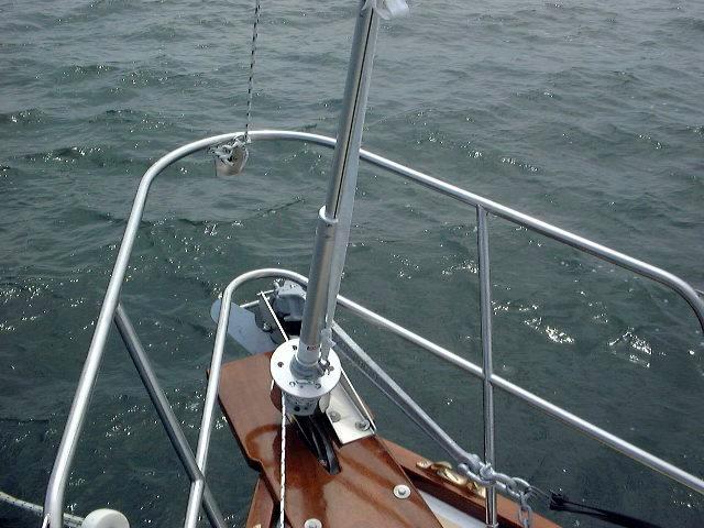 After
the mast was stepped, I completed the installation. All I had to do was
reinstall the parts of the drum, which I had left off during initial
installation to protect the components. The drum comes in four pieces--two
halves for the top and bottom sections--that simply screw together once inserted
in slots in the furling lower swivel. Then, the stainless steel line guard
could be installed. Of course, I had to be very careful not to drop
anything overboard! After
the mast was stepped, I completed the installation. All I had to do was
reinstall the parts of the drum, which I had left off during initial
installation to protect the components. The drum comes in four pieces--two
halves for the top and bottom sections--that simply screw together once inserted
in slots in the furling lower swivel. Then, the stainless steel line guard
could be installed. Of course, I had to be very careful not to drop
anything overboard!
|
|
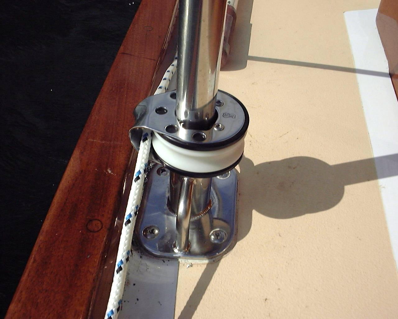
 I
finally got the drum completely installed. It took a little while to get
the stainless guard aligned properly--it was tough getting the allen screws
started in the tight space beneath the drum. Plus, everything is 100 times
harder when you're surrounded by water. I
finally got the drum completely installed. It took a little while to get
the stainless guard aligned properly--it was tough getting the allen screws
started in the tight space beneath the drum. Plus, everything is 100 times
harder when you're surrounded by water.
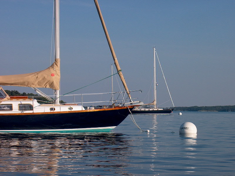
Once that was done, I led the furling line aft
through a series of block (see below) to the cockpit. with everything set
up, I called my sailmaker to come out and take final measurements for the new
genoa I had ordered months before. We had agreed that we wanted to make
sure that the hoist was exactly right, and that meant having the mast stepped
and furler installed to be sure. However, I only had to wait a few days
for my sail to be completed. When it was, I hoisted it up and tried my new
gear. It was wonderful, although it looked like maybe I'd have to adjust
the placement of the forwardmost block a little bit.
|
|
 When I installed the lifelines and stanchions,
I also installed some neat Schaefer Clear Step guide blocks. They slip
over the tops of the stanchions and are secured wherever you want them with a
set screw. These keep the roller furling line out of the way.
There are three of these blocks--one on each stanchion--plus a spring-mounted
block on the pulpit. These are part of a kit I purchased for my Schaefer
unit, although the kit comes only with two stanchion blocks, so I bought a third
separately. When I installed the lifelines and stanchions,
I also installed some neat Schaefer Clear Step guide blocks. They slip
over the tops of the stanchions and are secured wherever you want them with a
set screw. These keep the roller furling line out of the way.
There are three of these blocks--one on each stanchion--plus a spring-mounted
block on the pulpit. These are part of a kit I purchased for my Schaefer
unit, although the kit comes only with two stanchion blocks, so I bought a third
separately.
|
|
 We
have now used the system for a full season. We are extremely happy with
it--it rolls very easily, and has never been a problem. No maintenance was
required. I rerouted the furling line slightly after I found that the line
would sometimes become too loose when unfurling, which allowed it to once get
stuck at the forward side of the drum. I was easily able to clear the
snag, and I noticed it before it became any more of a problem. Moving the
pulpit-mounted spring block further forward provided a better lead, and the
system was flawless thereafter. We
have now used the system for a full season. We are extremely happy with
it--it rolls very easily, and has never been a problem. No maintenance was
required. I rerouted the furling line slightly after I found that the line
would sometimes become too loose when unfurling, which allowed it to once get
stuck at the forward side of the drum. I was easily able to clear the
snag, and I noticed it before it became any more of a problem. Moving the
pulpit-mounted spring block further forward provided a better lead, and the
system was flawless thereafter.
|
|