|
Pulpits, Stanchions, and
Lifelines
This page was last
updated on 9 February 2008
Update: After 6
seasons' use, I replaced the lifelines. Click here
for more.
Glissando
came with a bow pulpit
and two stanchions on each side, with lifelines terminating at deck level just
forward of the cockpit. It was obvious from the start that additional
stanchions and a stern pulpit were going to be necessary. None of these
components were installed when the boat was purchased, as they had been removed
by the former owner at the beginning of his deck project. The stainless
steel original stanchions and sweeping bow pulpit were in good condition, although
the shape of the pulpit was dated. The lifelines were what you might
expect after 37 years. When the boat was delivered home, these items were
the last thing on my mind, and I stored them out of the way somewhere.
|
|
 As
work on the project progressed, and the desired finish quality and appearance
became an increasing issue, I decided that perhaps going with a new bow pulpit
would be a good idea. The old pulpit was very dated in appearance, and was
fairly low. A new pulpit with a more upright shape would be more secure
and better looking. As
work on the project progressed, and the desired finish quality and appearance
became an increasing issue, I decided that perhaps going with a new bow pulpit
would be a good idea. The old pulpit was very dated in appearance, and was
fairly low. A new pulpit with a more upright shape would be more secure
and better looking.
Of course, one thing leads to
another, and while looking at pulpits and stanchions I gave more thought to the
height issue. The old stanchions are 24" high, which is really
fine. However, higher is better. I knew we needed two additional stanchions
so we could extend the lifelines to the new stern pulpit, and, when I figured in
the desire for double lifelines, it was evident that I might as well just buy
all new stanchions as well. This would enable me to increase the height
slightly to 26" and go with double lifelines.
There is no cheap way out of this
unless you want to endlessly scrounge, something I am generally not inclined to
do for any length of time (and I call myself a Triton owner...). I knew
about a company that specialized in building rails and the like for sail and
powerboats, Tops in Quality, and,
after browsing their website, decided to go ahead. They have several
different pulpit configurations and styles, along with different stanchion
options. I asked for, and received, a quote for the various pieces, and
found out that they offer a 20% discount for a "whole boat order",
meaning two pulpits and stanchions. This cemented my decision to go with
them, as well as my earlier decision to replace the existing stanchions with
new. They did not have standard measurements, so I carefully measured the
places called for in their measuring guide and placed the order.
|
|
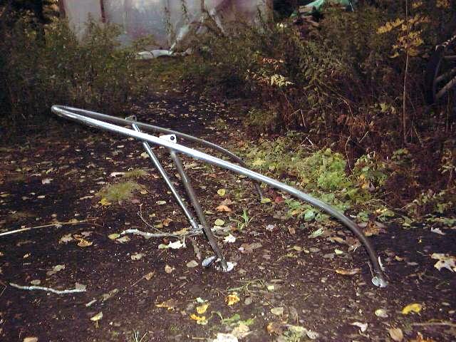
 Although
the order took longer to arrive than anticipated, it did not matter, as I had
lots of other things to do--and still do, as of this writing. The new pulpits
were shipped motor freight to a nearby terminal, where I picked them up; they
will ship to a residence for an additional fee. It was with much
trepidation that I brought them out to the boat...would the new pulpits fit
according to my measurements, or had I screwed up? Although
the order took longer to arrive than anticipated, it did not matter, as I had
lots of other things to do--and still do, as of this writing. The new pulpits
were shipped motor freight to a nearby terminal, where I picked them up; they
will ship to a residence for an additional fee. It was with much
trepidation that I brought them out to the boat...would the new pulpits fit
according to my measurements, or had I screwed up?
|
|
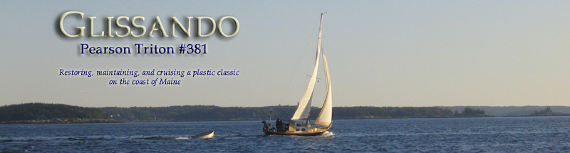
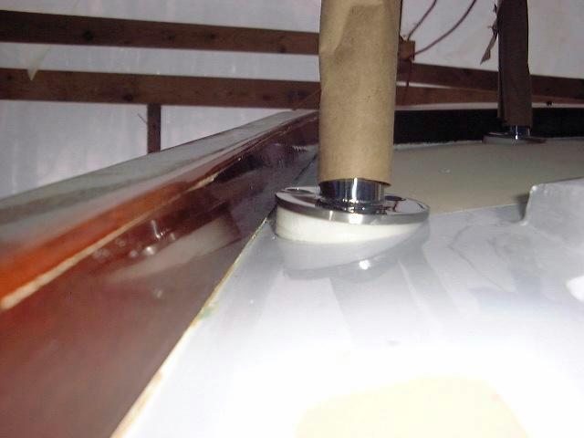
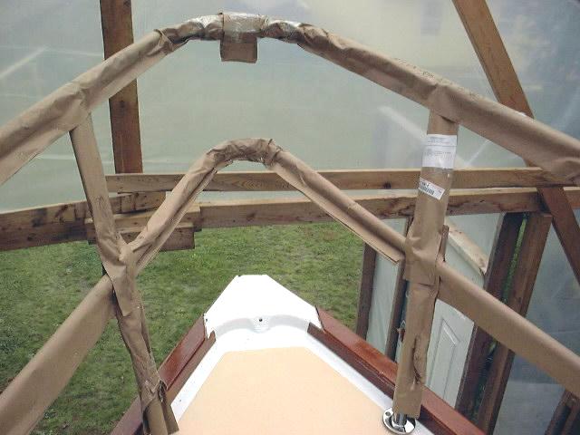
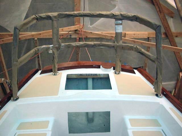 Thankfully, the measurements I
took were right, and the only problem--relatively minor--was that there had been
no provision on the measuring guide to take into account the camber of the deck Thankfully, the measurements I
took were right, and the only problem--relatively minor--was that there had been
no provision on the measuring guide to take into account the camber of the deck  aft.
It looks pretty flat, but is actually angled significantly enough to cause
the welded bases of the new stern pulpit to fail to fit flush. Not a big
deal--I'll just have to cut some wedge-shaped pieces to make up the angle. See
below for this process. Other than that, the pulpits look great and appear to fit well.
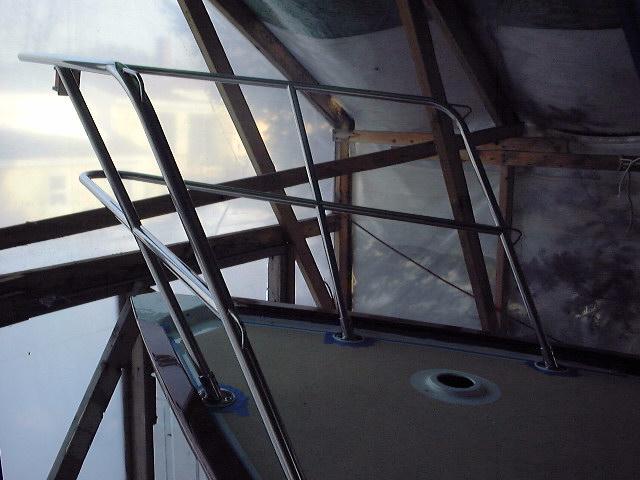
The new pulpits have integral
running lights and double rails, and feature all welded construction. The stanchions feature a flat top with integral holes for
running double lifelines, and large welded bases, to which the stanchions are
secured with double set screws. The stanchion bases are angled inward 5
degrees to accommodate the deck camber--a standard measurement. They won't
actually be installed for a little while yet. aft.
It looks pretty flat, but is actually angled significantly enough to cause
the welded bases of the new stern pulpit to fail to fit flush. Not a big
deal--I'll just have to cut some wedge-shaped pieces to make up the angle. See
below for this process. Other than that, the pulpits look great and appear to fit well.
The new pulpits have integral
running lights and double rails, and feature all welded construction. The stanchions feature a flat top with integral holes for
running double lifelines, and large welded bases, to which the stanchions are
secured with double set screws. The stanchion bases are angled inward 5
degrees to accommodate the deck camber--a standard measurement. They won't
actually be installed for a little while yet.
I
mentioned my wedge problem to a friend, and he came up with the idea to use
some synthetic material to form the wedges beneath the pulpit bases. He
even offered to get the material and cut the circles for me. He used a
3" hole saw to cut four circles of the white, smooth plastic
material--similar to Star Board or the stuff they make fish gutting boards out
of. The bases on the pulpit are just under 3" in diameter. Of
course, neither he nor I thought of the fact that z 3" hole saw leaves a
3" hole in the material being cut...but the plug inside the saw is actually
a little smaller. This means that the cut discs are just a little smaller
than the pulpit bases, but not enough to matter.
I needed four wedges: two
that were 1/2" thick at one side, and tapered to nothing at the other, for
the forward pulpit bases and two less severe ones for the aft bases. Of
course, cutting these angles presented a quandary: how to do it?
Sanding was out because, being plastic, the material tends to gum up sandpaper
in short order. Using a saw seemed to be the way to go, and to do so
safely and accurately required building a simple jig.
|
|
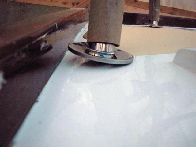
 First,
I drew the profile of the wedge on a board and set the saw blade to the proper
angle (10 degrees for the forward pair; 7 degrees for the aft pair) and cut a sample,
which I test fit on the boat. Next, using a hot melt glue gun, I glued two
of the discs to a wide scrap of board, and glued small blocks ahead and behind
the discs, trapping them in place. I then glued a third board on the outside,
completely encapsulating the two discs in the wood jig. I used a piece of
the scrap that I had used to test the angle to help set the saw fence at the
proper distance, and First,
I drew the profile of the wedge on a board and set the saw blade to the proper
angle (10 degrees for the forward pair; 7 degrees for the aft pair) and cut a sample,
which I test fit on the boat. Next, using a hot melt glue gun, I glued two
of the discs to a wide scrap of board, and glued small blocks ahead and behind
the discs, trapping them in place. I then glued a third board on the outside,
completely encapsulating the two discs in the wood jig. I used a piece of
the scrap that I had used to test the angle to help set the saw fence at the
proper distance, and  ran the jig through the saw, cutting an identical angle and profile on each of
the discs. I followed the same steps to cut the wedges for the aft pulpit
bases, only changing slightly the angle of the saw blade and the distance from
the fence to get the proper size. The finished wedges will pretty much
disappear once they are installed beneath the bases.
ran the jig through the saw, cutting an identical angle and profile on each of
the discs. I followed the same steps to cut the wedges for the aft pulpit
bases, only changing slightly the angle of the saw blade and the distance from
the fence to get the proper size. The finished wedges will pretty much
disappear once they are installed beneath the bases.
|
|
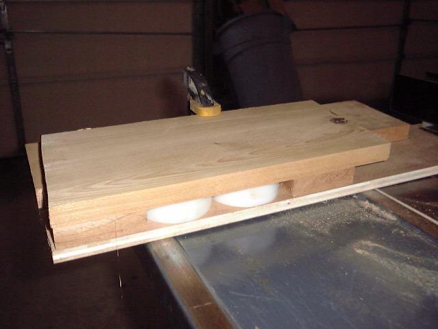
 Wedges
after cutting and some minor hand sanding to remove burrs... Wedges
after cutting and some minor hand sanding to remove burrs...
|
|
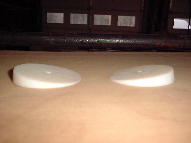
 Aft
port pulpit base and wedge... Aft
port pulpit base and wedge...
|
|
 Forward
starboard pulpit base and wedge... Forward
starboard pulpit base and wedge...
|
|
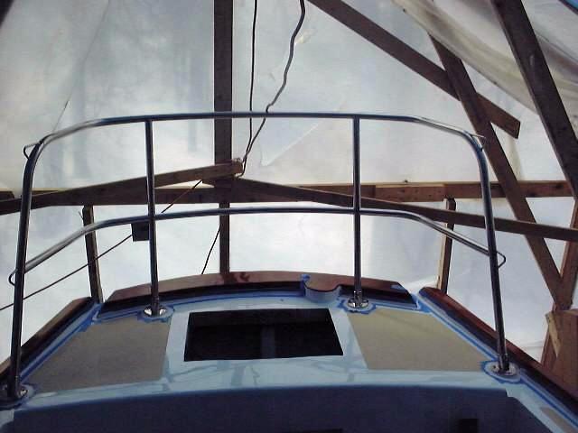
I installed
the pulpits
permanently on an unseasonably warm day in February. For
weeks, they had been driving me crazy--especially the stern pulpit, which always
seemed to be in the way in the cockpit. I couldn't wait to have them
installed and done with.
I began with the stern pulpit.
Installation was somewhat complicated because of the plastic base wedges--just
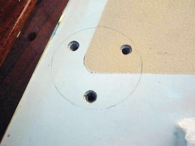
one more thing to have to drill holes in and deal with. First, I set up
the pulpit on top of the wedges and moved it around until it was in the proper
position and symmetrical on either side of the boat. Then, carefully, I
marked the outlines of the bases on the deck with a pencil to aid in
repositioning later, and began drilling the boltholes. I planned to tap
all the holes for the screw threads, so I drilled with a slightly smaller bit
size (15/64") for the 1/4-20 machine screws that will install the
bases. This hole turned out to be a little larger than desired.
After drilling the first hole in the first base, I inserted another drill bit to
simply hold the alignment while I drilled the other holes. I followed this
procedure on all four bases, being careful to ensure that the pulpit stayed in
its proper position and was not jarred out of alignment.
|
|
 With
the initial pilot holes drilled, I removed the pulpit and enlarged the holes in
the plastic wedges with a 1/4" bit--these will not be tapped. Next, I
used a 1/4-20 tap to tap the 12 mounting holes; the fiberglass is amazingly thin
on the aft deck, so there were fewer threads than I might have liked. Once
the holes were tapped, I drilled a slight countersink at the top of each hole
with a countersink bit; this recess will provide for a little pocket of sealant
right around the screw hole and will help the whole arrangement seal more
effectively. I then drilled holes in four plywood backing plates, making
the holes larger than necessary to help account for the fact that all the screws
did not go in perfectly straight, rather going in at a slight angle through the
bases. With
the initial pilot holes drilled, I removed the pulpit and enlarged the holes in
the plastic wedges with a 1/4" bit--these will not be tapped. Next, I
used a 1/4-20 tap to tap the 12 mounting holes; the fiberglass is amazingly thin
on the aft deck, so there were fewer threads than I might have liked. Once
the holes were tapped, I drilled a slight countersink at the top of each hole
with a countersink bit; this recess will provide for a little pocket of sealant
right around the screw hole and will help the whole arrangement seal more
effectively. I then drilled holes in four plywood backing plates, making
the holes larger than necessary to help account for the fact that all the screws
did not go in perfectly straight, rather going in at a slight angle through the
bases.
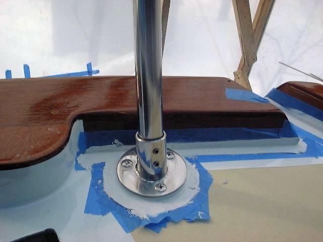
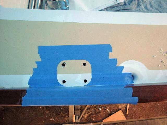
With this work done, I taped around the
outlines of the bases that I marked earlier, to keep excess sealant off the
decks and make cleanup easier. I also taped off part of the mahogany
toerail and the deck beneath, since there is a gap there that requires caulking
(another project I've put off forever) and, with the pulpit installed, caulking
the gap later would be difficult. Thus, I caulked the stern area just
before installing the pulpit. After cleaning all the surfaces with
solvent, I applied beads of polysulfide sealant to the deck in way of all the
bases, and pressed the wedges into place on top. I then sealed the top of  the
wedges and installed the pulpit over that. Because of the threaded screw
holes, I was able to pull the bases more or less tightly into the sealant from
above--one of the major advantages of this extra step. Note that I drilled
an extra hole through the center of the deck beneath the starboard aft pulpit
base to allow the stern light wires to run through. the
wedges and installed the pulpit over that. Because of the threaded screw
holes, I was able to pull the bases more or less tightly into the sealant from
above--one of the major advantages of this extra step. Note that I drilled
an extra hole through the center of the deck beneath the starboard aft pulpit
base to allow the stern light wires to run through.
|
|
 Next,
I positioned myself upside down and beneath the deck (having the lazarette hatch
cut in the top of the deck is a Godsend here...) and installed the backing
plates, fender washers and nuts. The two aft bases ended up right above a
wooden beam that I epoxied beneath the deck to help support the new hatch
opening in an earlier project, so I couldn't fit backing plates there.
I'll have to come up with a more permanent solution there, but for now I
installed the nuts and washers alone. I tightened everything down fairly
tight, but left the final tightening for later, after the caulk has set
up. I spent a little Next,
I positioned myself upside down and beneath the deck (having the lazarette hatch
cut in the top of the deck is a Godsend here...) and installed the backing
plates, fender washers and nuts. The two aft bases ended up right above a
wooden beam that I epoxied beneath the deck to help support the new hatch
opening in an earlier project, so I couldn't fit backing plates there.
I'll have to come up with a more permanent solution there, but for now I
installed the nuts and washers alone. I tightened everything down fairly
tight, but left the final tightening for later, after the caulk has set
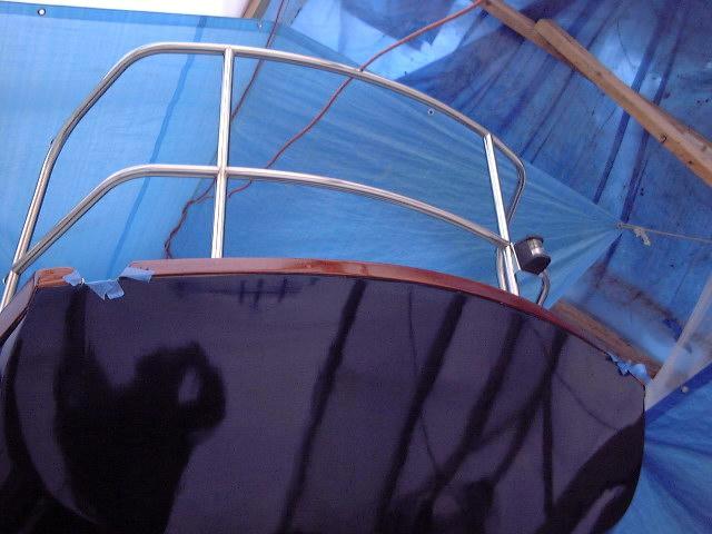
up. I spent a little  time
cleaning up the excess sealant on deck around the bases and wedges. With
this done, I could finally remove the packing material from the rails and get a
glimpse of my shiny new pulpit. time
cleaning up the excess sealant on deck around the bases and wedges. With
this done, I could finally remove the packing material from the rails and get a
glimpse of my shiny new pulpit.
I installed the bow pulpit just a little
differently. The first major difference is that the foredeck is cored,
while the poop deck is solid. Therefore, I first had to mark and drill the
holes slightly oversize and remove the core from the area, and then fill the
holes with epoxy and let it kick overnight. With this done, I redrilled
the holes, this time with a 13/64" bit, and tapped them with the 1/4-20 tap
as before. This process left me with nice, solid threaded holes that took
the machine screws well. As before, I countersunk the tops a little bit to
allow for that sealant pocket.
|
|
 I
also removed the bases from the pulpit. While the pulpits are all welded,
the bases themselves are held on with setscrews, so removal was easy.
Removing the bases meant that not only could I seal and install a single base at
a time--much easier than four--but could also drill screw from straight above,
without any obstructions. This provided a better, cleaner
installation. Otherwise, I followed the above steps exactly--taping around
each hole, sealing the gap beneath the wood toerail, then sealing the bases and
screwing them down. The full-length tapped holes gripped the screws
beautifully, and I got a tight fit just from screwing down from above.
This made it easy (and possible) for me to install the pulpit buy myself, since
I didn't need and extra hand belowdecks to deal with the nuts. Once all
four bases were attached from the top, I went below and installed backing
plates, fender washers and nuts, taking my time and easily snugging the nuts
without a helping hand to hold the screw from above. I left the excess
bead of caulk that squeezed out for trimming later; plus, I'll resnug the nuts when
he caulk is cured. I
also removed the bases from the pulpit. While the pulpits are all welded,
the bases themselves are held on with setscrews, so removal was easy.
Removing the bases meant that not only could I seal and install a single base at
a time--much easier than four--but could also drill screw from straight above,
without any obstructions. This provided a better, cleaner
installation. Otherwise, I followed the above steps exactly--taping around
each hole, sealing the gap beneath the wood toerail, then sealing the bases and
screwing them down. The full-length tapped holes gripped the screws
beautifully, and I got a tight fit just from screwing down from above.
This made it easy (and possible) for me to install the pulpit buy myself, since
I didn't need and extra hand belowdecks to deal with the nuts. Once all
four bases were attached from the top, I went below and installed backing
plates, fender washers and nuts, taking my time and easily snugging the nuts
without a helping hand to hold the screw from above. I left the excess
bead of caulk that squeezed out for trimming later; plus, I'll resnug the nuts when
he caulk is cured.
With both pulpits installed, I made the final
wiring connections for the running lights with the wires I ran earlier.
I spent a fair
bit of
time deciding where to locate my new stanchion bases. The original
locations would not work out properly, since I was adding a third stanchion to
each side, and ideally I wanted them to end up evenly spaced between the
pulpits. Fine--no problem...except for working around the genoa sheet
tracks. The original tracks were located on the sidedeck in prime
stanchion-location territory, and I solicited much advice from fellow Tritoners
as to how to proceed.
I ended up deciding to locate my new genoa
tracks on top of the toerail, which frees up the sidedeck for stanchions
wherever I want. Details of the genoa track installation are located here.
With three bases, and the pulpits I have, the spacing ends up at about 77"
between base centers. I adjusted things a little to account for the actual
lifeline spans, which will be longer on the forward and aftermost sections
because of the angle of the pulpits. Roughly, the first base is located
just aft of the front of the cabin trunk; the second base is in line with the
forward edge of the forward port in the salon; and the after base is 6-3/4"
forward of the center of the sidedeck scupper. After mocking up this
layout, I decided it looked good and began the process of installation.
|
|
 Installing
the bases is a multi-step process. First, I laid the base in the proper
spot and marked the boltholes with a pencil. Next, I drilled small pilot
holes through the deck in the center of the marks, and then enlarged the holes
with a 3/8" drill bit. This provides me with the hole I need to
create the epoxy plug. I then covered the deck with tape, taping right
over the area beneath the base, and the adjacent toerail. Next, I put the
base back in place and traced around it, and cut out the inside part with a
utility knife. This gave me a nice tape border around the base
location. I did this for all six bases. Then, I taped over the holes
from inside the boat. Installing
the bases is a multi-step process. First, I laid the base in the proper
spot and marked the boltholes with a pencil. Next, I drilled small pilot
holes through the deck in the center of the marks, and then enlarged the holes
with a 3/8" drill bit. This provides me with the hole I need to
create the epoxy plug. I then covered the deck with tape, taping right
over the area beneath the base, and the adjacent toerail. Next, I put the
base back in place and traced around it, and cut out the inside part with a
utility knife. This gave me a nice tape border around the base
location. I did this for all six bases. Then, I taped over the holes
from inside the boat.
I mixed up some thick epoxy and put it in all
the boltholes, cleaning up any excess. When this kicks, I will end up with
a nice solid plug, through which I can drill the actual boltholes. This
will protect the core in the event that the bolts leak. I left the epoxy
to cure overnight.
|
|
The next step was to drill for the new
boltholes, using a 13/64" bit. Holding the stanchion base in place, I
drilled each hole. Then, I tapped the holes with a 1/4-20 tap, and cut a
shallow countersink at the top of each hole to provide a little pocket for
sealant to fill right around the bolt. I laid on a heavy bead of
polysulfide caulk, and installed the base with four 1/4" bolts. The 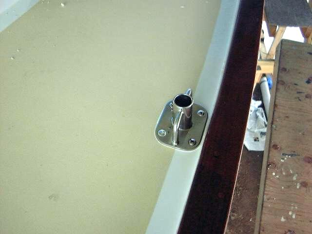 neat thing about tapping the holes is that I can tighten the bolts from above
without having to worry about immediately getting nuts and washers on from
below; also, installing the nuts is easy because the bolts don't spin from
beneath. I cleaned up all the sealant that squeezed out, removed the tape
and did a final cleaning of the area.
neat thing about tapping the holes is that I can tighten the bolts from above
without having to worry about immediately getting nuts and washers on from
below; also, installing the nuts is easy because the bolts don't spin from
beneath. I cleaned up all the sealant that squeezed out, removed the tape
and did a final cleaning of the area.
When all six bases were installed, I went
below and installed some 1/2" plywood backing plates I had made, along with
fender washers and nuts. I tightened everything securely. In the vee
berth, where the backing plates are visible, I spray painted them with
chrome-look spray paint to match the stainless bolts.
Next, I installed the three stanchions on each
side, and temporarily tightened the setscrews in the bases. We plan upper
and lower lifelines, with opening gates on each side between the last stanchion
and the stern pulpit. To measure for the new lifelines, I taped my tape
measure to the aft side of the last stanchion, and ran it up to the bow pulpit
along the outsides of the stanchions. I did this for both sides, upper and
lower lifelines, and noted the measurements. Then, I measured for the
gates between the aft end of the last stanchion and the stern pulpit. The
new lifelines are on order from my rigger, and should be in in a couple
weeks. I'll wait for permanent installation until just before the boat is
launched, as the stanchions are in the way with the boat in the shed.
|
|
Lifelines
and Stanchions
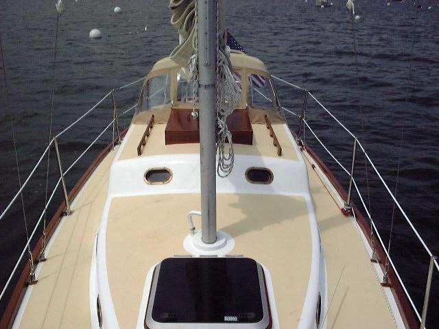 The
day before launching, I installed the lifelines and stanchions. I had
received them some weeks before, and had trial fit everything--the gates
required shortening by a small amount--so I knew everything would fit. The
day before launching, I installed the lifelines and stanchions. I had
received them some weeks before, and had trial fit everything--the gates
required shortening by a small amount--so I knew everything would fit.
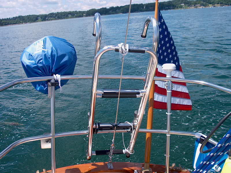
We purchased double lifelines, 5/16"
total diameter with the vinyl coating. There are adjusting turnbuckles at
the forward ends, and opening gates between the last stanchion and the stern
pulpit. The gates use the new Johnson over-center pelican hooks that are
easy to release under pressure. They work great.
The stanchions are held in place with double
setscrews at each location, and the lifelines just feed through after unscrewing
the eye at the aft end. Very nice.
|
|
| Stern Pulpit & Portable
Ladder |
Bow Pulpit & |
Lifelines |
 |
 |
 |
|
Update: Winter
2008I decided to replace the
lifelines. Though the originals were only in use for 6 on-water seasons,
the vinyl coating was beginning to show wear where it passed through the
stanchions, and telltale signs of internal wire corrosion were becoming visible
at the ends of the wires, where the vinyl coating ended at the swaged terminal
studs.
In addition, a collision involving another boat
back in 2003 had damaged both the upper and lower lifelines on the starboard
side. (Link to the
original incident) It was this damage more than anything that led me
to decide to replace the lifelines now, in a very conservatively-timed upgrade
schedule.
The trend since I'd had the first lifelines
made had made a move towards uncoated 1x19 stainless steel wire for lifelines,
an offshoot of the various racing rules and offshore requirements, but one that
made good sense in a lot of ways. After all, it's the vinyl coating that
is the death knoll for most lifelines: the vinyl not only traps moisture
within, causing corrosion to the wire, but also deviously hides the damage
until, in many cases, it's too late. Therefore, I decided to follow the
current wave of thinking and go with uncoated wire for my lifelines.
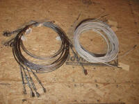
As before, I had
Maloney Marine
Rigging make up the new lifelines. Fortunately, he'd built the
original lifelines with intelligent forethought, and with only simple threaded
studs at each end of the old wires, reuse of the turnbuckles and fittings--the
most expensive part of the materials procurement--was straightforward and
represented a significant savings. The old fittings and hooks were still
in excellent condition. The new lifelines, seen in coils to the left next
to the old ones on the right, were 1x19 alloy 316SS uncoated wire, 3/16" in
diameter. |
|
|
|