|
Yanmar
SB12: Engine Template
This page was last updated on 4 May 2000.
|
|
Installing the new engine
requires constructing new mounts. Getting the alignment, position and
angle right is difficult and finicky at best, so I decided to build a rough
template of the engine to assist me. The most important features of the
engine--the mount locations and the transmission coupling position--are
accurately laid out on the template. In addition, I included rough
representations of the cylinder head position and height, the oil pan, and the
transmission gear housing, all of which may affect the ultimate position of the
engine.
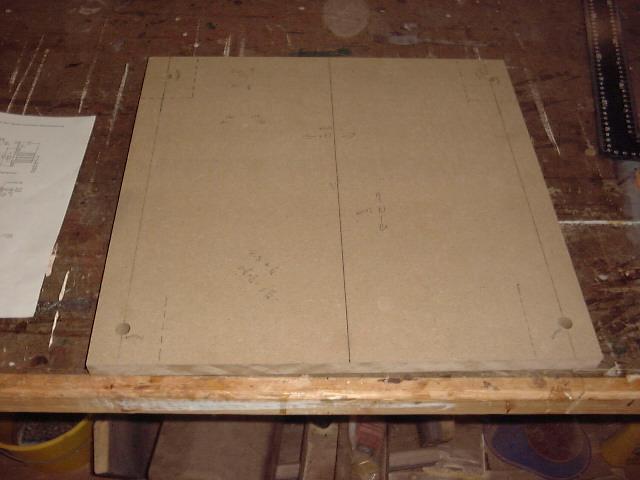 Using
the service manual I purchased for the engine, I consulted the drawings showing
the dimensions of the engine and bolting flanges. I started with a scrap
piece of MDF, which I cut to size to represent the four corners of the engine
determined by the mounting flanges. The Yanmar SB-12 fortunately features
mounts that are in line with each other fore and aft, which makes for a simple
rectangular plywood template. With the panel cut to the exact size of the
outline of the mounts, I then located the hole centers (using the measurements
on the supplied drawings) and drilled the holes on my drill press. Using
the service manual I purchased for the engine, I consulted the drawings showing
the dimensions of the engine and bolting flanges. I started with a scrap
piece of MDF, which I cut to size to represent the four corners of the engine
determined by the mounting flanges. The Yanmar SB-12 fortunately features
mounts that are in line with each other fore and aft, which makes for a simple
rectangular plywood template. With the panel cut to the exact size of the
outline of the mounts, I then located the hole centers (using the measurements
on the supplied drawings) and drilled the holes on my drill press.
|
|
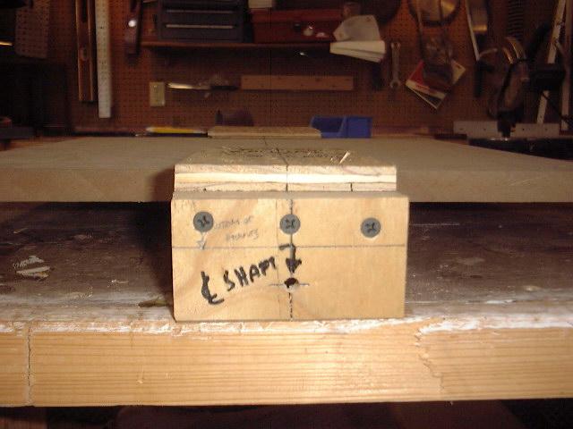
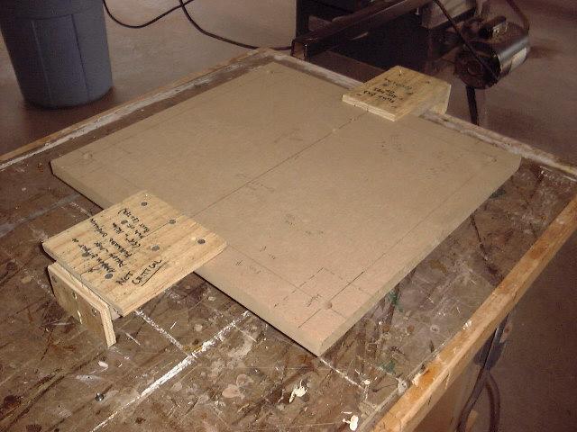 Next,
I screwed some extensions to the basic form. Two extensions were
installed, one at each end, to represent the locations of the furthest forward
part on the engine (the accessory pulley) and the transmission coupling at the
aft end. The forward (pulley) extension was fairly accurately represented,
although this measurement is not critical to the installation. The
coupling extension, however, was extremely carefully measured so that the end is
exactly representative of the face of the coupling on the engine. With
these simple extensions screwed to the platform (attached with the scraps of
plywood you see here) I added short plywood ends to both extensions, shown below Next,
I screwed some extensions to the basic form. Two extensions were
installed, one at each end, to represent the locations of the furthest forward
part on the engine (the accessory pulley) and the transmission coupling at the
aft end. The forward (pulley) extension was fairly accurately represented,
although this measurement is not critical to the installation. The
coupling extension, however, was extremely carefully measured so that the end is
exactly representative of the face of the coupling on the engine. With
these simple extensions screwed to the platform (attached with the scraps of
plywood you see here) I added short plywood ends to both extensions, shown below as the vertical piece. These are used to exactly locate the center of the
propeller shaft and, therefore, the coupling. With the centers marked,
again using the measurements on the shop drawing, I drilled small holes through,
to allow an alignment string to pass through both ends of the
template. The string, which will be installed through the shaft log and
into the boat, will be used to properly orient the engine and the wooden
foundation that will be constructed.
as the vertical piece. These are used to exactly locate the center of the
propeller shaft and, therefore, the coupling. With the centers marked,
again using the measurements on the shop drawing, I drilled small holes through,
to allow an alignment string to pass through both ends of the
template. The string, which will be installed through the shaft log and
into the boat, will be used to properly orient the engine and the wooden
foundation that will be constructed.
|
|
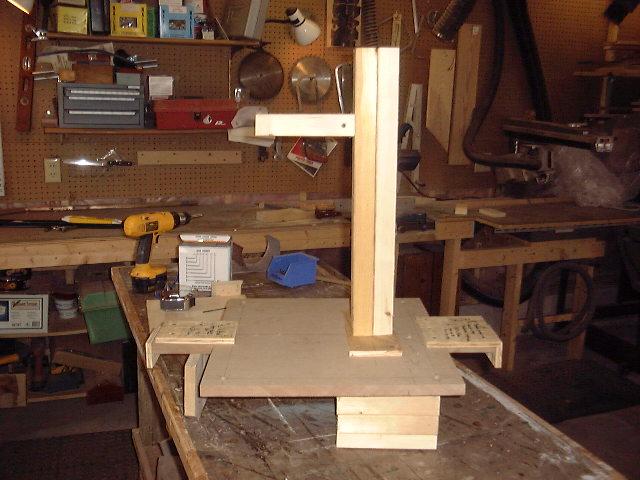 Next,
I added some rough representations of some of the other engine components that
will in part determine its position in the boat. Using the drawings, and
consulting the engine itself from time to time, I built the very simple, crude
shapes you see in the photo to represent the height and rough position of the
cylinder head, exhaust manifold (the short horizontal piece near the top of the
tall "cylinder head"), the oil pan and transmission housing.
These are important to the installation because they will determine exactly how
far aft or forward the engine has to be located to properly clear the hull and
cockpit structure. This is the finished template. I know it looks
funny, but it will be of great help as I continue the installation. Once I
determine the basic position of the engine in the boat, and the minimum heights
and positions of the foundation, I may remove some of the extra pieces, leaving
only the plywood bolting template and shaft centers. Next,
I added some rough representations of some of the other engine components that
will in part determine its position in the boat. Using the drawings, and
consulting the engine itself from time to time, I built the very simple, crude
shapes you see in the photo to represent the height and rough position of the
cylinder head, exhaust manifold (the short horizontal piece near the top of the
tall "cylinder head"), the oil pan and transmission housing.
These are important to the installation because they will determine exactly how
far aft or forward the engine has to be located to properly clear the hull and
cockpit structure. This is the finished template. I know it looks
funny, but it will be of great help as I continue the installation. Once I
determine the basic position of the engine in the boat, and the minimum heights
and positions of the foundation, I may remove some of the extra pieces, leaving
only the plywood bolting template and shaft centers.
Next: determining the rough position of
the engine in the boat, and roughing out the foundation.
|
|
|
Please click here to
continue.
|
|