|
Deck Trim (Page 2)
|
|
Cockpit
Coamings
 The
original cockpit coamings at first appeared to be in salvageable
condition. When we bought the boat, the coamings were loosely
installed--no screws--and, compared to the rest of the boat at that time, they
looked positively great. An attempt had been made by the previous owner to
strip, sand and refinish the coamings, and I thought I would just resand the
pieces, varnish and reinstall. As with so many other things, my initial
feelings were to change. The
original cockpit coamings at first appeared to be in salvageable
condition. When we bought the boat, the coamings were loosely
installed--no screws--and, compared to the rest of the boat at that time, they
looked positively great. An attempt had been made by the previous owner to
strip, sand and refinish the coamings, and I thought I would just resand the
pieces, varnish and reinstall. As with so many other things, my initial
feelings were to change.
|
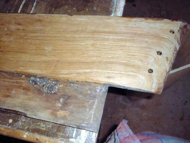 As
soon as the boat got delivered home after the trip from the island, I pulled the
coamings off and put them, along with other trim pieces, in storage to deal with
later. During the first winter, I pulled them out and began to look them
over more closely, and at that point decided to replace them in entirety.
Despite their initial appearance, closer inspection revealed a nasty split in
the wood at the forward end of one coaming, the built up blocks at the forward
end (where they turn and run into the cabin trunk) were all exposed end grain
and looked terrible, there were exposed screws from the
"whatweretheythinking" construction technique used to attach the
forward blocks (why would you ruin a nice piece of solid wood with ugly,
misaligned exposed screw heads?), the grain of the wood was rough and weather-beaten
(the soft summer grain was mostly worn away, leaving the tough, hard,
unattractive winter grain) and the coamings' thickness was severely reduced from
years of weather, scrubbing and sanding. They would not ever be able to be
restored in keeping with the rest of the project, so I decided to replace them. As
soon as the boat got delivered home after the trip from the island, I pulled the
coamings off and put them, along with other trim pieces, in storage to deal with
later. During the first winter, I pulled them out and began to look them
over more closely, and at that point decided to replace them in entirety.
Despite their initial appearance, closer inspection revealed a nasty split in
the wood at the forward end of one coaming, the built up blocks at the forward
end (where they turn and run into the cabin trunk) were all exposed end grain
and looked terrible, there were exposed screws from the
"whatweretheythinking" construction technique used to attach the
forward blocks (why would you ruin a nice piece of solid wood with ugly,
misaligned exposed screw heads?), the grain of the wood was rough and weather-beaten
(the soft summer grain was mostly worn away, leaving the tough, hard,
unattractive winter grain) and the coamings' thickness was severely reduced from
years of weather, scrubbing and sanding. They would not ever be able to be
restored in keeping with the rest of the project, so I decided to replace them. |
|
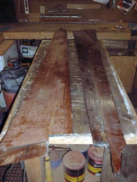
I ordered some wide mahogany
planks from my hardwood supplier. At first, I worried about the
availability of such wide boards (over 12" necessary), and I loathed the
thought of having to glue a couple boards together. When I mentioned the
width I needed, the guy on the phone didn't even blink (or so I imagined); I
hadn't told him what the wood was for, but he said they usually stocked wide
boards for boatbuilders who needed cockpit coamings! Anyway, I was in
luck, and the cost wasn't too horrible. The beautiful, wide, long boards
were delivered along with the rest of my wood supplies for the interior work,
and, since I was not yet ready to work on the coamings, I put them into storage
for a while.
 Months
later, it was time to begin the coaming construction. Using the old
coamings as a guide (I removed the solid blocks from the forward ends first so
the coamings could lay flat), I traced the outline of the coamings onto the new
wood. I traced the cutouts at each end, and the decorative curve at the
aft end, but for the top edge, I marked the forward and aft ends and used a long
straightedge to connect the marks. The old coamings had a slight concave
curve at the top end (maybe a half inch of sweep), but I elected to keep the
straight line, as it is much easier to cut smoothly and I don't think it will be
noticeable anyway. I kept the straight bottom edge line aligned with the
straight edge of the new board. Months
later, it was time to begin the coaming construction. Using the old
coamings as a guide (I removed the solid blocks from the forward ends first so
the coamings could lay flat), I traced the outline of the coamings onto the new
wood. I traced the cutouts at each end, and the decorative curve at the
aft end, but for the top edge, I marked the forward and aft ends and used a long
straightedge to connect the marks. The old coamings had a slight concave
curve at the top end (maybe a half inch of sweep), but I elected to keep the
straight line, as it is much easier to cut smoothly and I don't think it will be
noticeable anyway. I kept the straight bottom edge line aligned with the
straight edge of the new board.
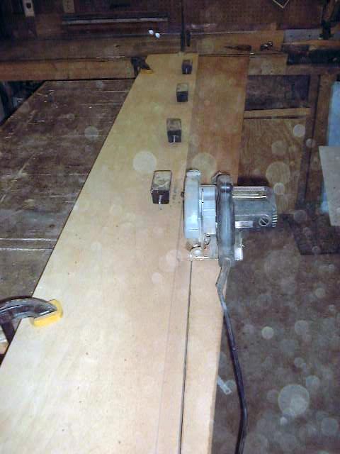
Once the pieces were marked, I
set up a straightedge along the top mark and offset it by 1 1/8"--the width
of the narrow edge of my circular saw table. To cut, I ran the saw table
up against the straightedge (a wide strip of plywood with a pristine factory
edge) and cut away. I cut the end cuts and curves with a jigsaw.
With the coamings cut to shape
but still generally rough, it was time to do a preliminary fit in the
cockpit. First, I used a sander to remove some material from the side of
each coaming where it rests against the fiberglass in the cockpit, to match the
originals. This stock removal allows the coamings to tuck right into the
forward and after corners of the cockpit, which are slightly rounded.
Because the sides of the cockpit are curved, the coamings must be bent somewhat
to fit; I could press them mostly into place by hand, but some mechanical
assistance would be necessary to hold them for installation. The
preliminary dry fit showed a need to remove a little more material than I had at
the corners--I caused a slight splinter at the forward end on the port side when
trying to push the coaming into place, so I brought the coamings back to the
shop and sanded as necessary. Fortunately, the splinter remained attached, and
when I glue it back down it won't even be noticeable.
|
|
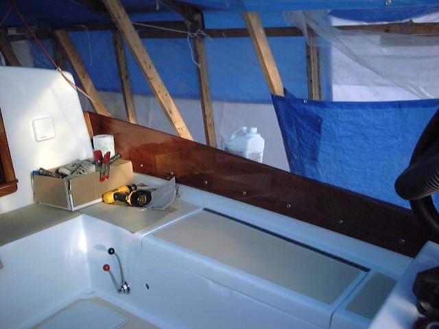
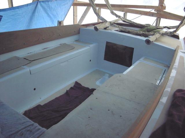
When reinstalled, the coamings
now looked like they would fit nicely once they were bent into place. To
do the bending, I cut two boards to jam the forward and aft ends into place, and
cut a 2x4 slightly shorter than the distance between the middle of the
coamings. Using the jack from my truck, I pressed the coamings into the
middle portion of the curve; it was effortless, and pretty much closed the
entire gap except for a portion just forward of where the jack was installed; I
may have to move the jack to that area once I get some screws into the after
portion of the coamings. I left the assembly to sit over night, mainly
because I need to pick up some wood screws to secure the coamings.
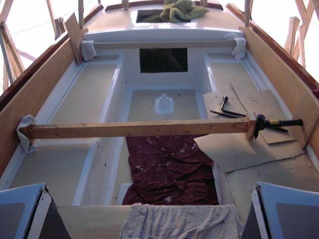
The next day, after spending way
too much on a set of # 12 x 2 1/2" stainless screws, I installed screws
with finishing washers in the coamings. When the coamings are permanently
installed, I will aplpy some caulking to the back side, but the screws will
allow me to remove them for refinishing as needed. Using the old coamings
as a guide, I measured the distance from the bottom edge to the screw holes
(2"), guestimated the spacing between the screws at 10" (12"
seemed too far; 6" too close) and cut a scrap of wood to 10"x2"
to use as a guide for marking the holes. Starting 3" from the aft
end, I marked holes up as far as the jack in the middle, and drilled them
out--first a smaller bit for a pilot hole through the mahogany and into the
fiberglass and wood backer, then a slightly larger drill through just the wood
to allow the screw to pass through the wood more easily. I installed the
first four screws (from aft forward), then I went ahead and removed the center
jack and replaced it slightly farther forward to press that portion of the
coaming into place. This done, I proceeded to install the remaining
screws. Through a stroke of luck, the final screw ended up 3" aft of
the forward end--so that the screw placement is symmetrical! I did not
calculate this, but it just happened.
|
|
 The screws held the coamings
nicely in place, with no signs of pulling out. This might be more of a
concern with inset and plugged screws, as they would be supported by less
material and no washers. The screws do not look bad in place with the
finishing washers, and removing the coamings every year for refinishing will
keep them looking good for at least another 30 years. The screws held the coamings
nicely in place, with no signs of pulling out. This might be more of a
concern with inset and plugged screws, as they would be supported by less
material and no washers. The screws do not look bad in place with the
finishing washers, and removing the coamings every year for refinishing will
keep them looking good for at least another 30 years.
|
 |
|
With the
coamings installed, I turned to making the thicker blocks at the forward end
that turn back in towards the cabin trunk. The old ones were poorly
made: that is, they were all end grain, wherever you looked. They
were built up from several 3/4" boards, and over time had blackened and
checked with the weather.
First, I tried the fit of the
old blocks (which I had removed from the old coamings) in the spaces left by the
new coamings. Neither one fit properly, so I took measurements (using the
old blocks as a rough template) for how much larger or smaller the new
blocks had to be. On the starboard side, the old block was up to 1/2"
narrower than the gap; on the port side, the fit was a little snug.
With my measurements in hand and
the old blocks as a template, I laid out some new pieces on a piece of 2"
thick mahogany I had left over from the forward hatch frame. I laid the
new pieces out so that the flat grain would be facing forward and aft, and the
less attractive and weather resistant end grain would be hidden against the
cabin trunk and coaming. The 2" thickness was deemed by me to be
thick enough, even though the originals were somewhat thicker--perhaps
3". I used a simple jig on my table saw to cut the angle--the other
long dimension is straight, where it meets the coaming--and cut the new pieces
overlong to allow for trimming to the exact size later.
Doing one block at a time, I
made numerous trips out to the boat and up the staging to test fit each
piece. Neither one fit perfectly the first time, and I had to cut an angle
on the bottom to allow the block to tip forward and correspond with the angle of
the front of the coaming. Finally, I got the pieces to fit well, after
nearly a dozen trips back and forth.
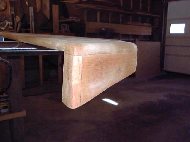
The exposed end grain at the top
edge would pose a problem if left alone, so I cut 3/4" off the top and
epoxied on a piece of 3/4" stock to cover the end grain. I cut the
aft-facing side to an angle to match the angle of the blocks, but I decided that
the forward side looked best if it was left straight, so that there will be a
little knuckle in the coaming when all is done. When the epoxy kicked, I
ground the overhanging piece flush with the blocks.
 After a week or so of waiting
for the dodger template to be made (the coamings are critical for the shaping of
the dodger), I removed the coamings from the boat for further work. The
first thing I did was glue the coaming blocks in place with thickened epoxy,
which I clamped overnight. Because it would be next to impossible to sand
the inside corner where the blocks meet the coamings, I took care to clean up
any epoxy that oozed out there before it had a chance to cure. Next, after
the epoxy kicked,
I sanded the top of the blocks flush with the coamings--they had purposefully
been made a little oversize--and sanded any epoxy that had squeezed out of the
joint. Then, I rounded the top edges and bottom inside edges of the
coamings with a 1/4" roundover bit in my router. To clean up the
forward end and make a nice, smooth transition between the block and the
coaming, I routed a 3/4" radius on the vertical edge. Then, I spend
some time sanding the coamings thoroughly, first with 80 grit, then 120, and
finishing with 220. Then, I applied ten coats of Epifanes gloss to each
side of the coamings. This took a couple months, elapsed time. There
was no rush. After a week or so of waiting
for the dodger template to be made (the coamings are critical for the shaping of
the dodger), I removed the coamings from the boat for further work. The
first thing I did was glue the coaming blocks in place with thickened epoxy,
which I clamped overnight. Because it would be next to impossible to sand
the inside corner where the blocks meet the coamings, I took care to clean up
any epoxy that oozed out there before it had a chance to cure. Next, after
the epoxy kicked,
I sanded the top of the blocks flush with the coamings--they had purposefully
been made a little oversize--and sanded any epoxy that had squeezed out of the
joint. Then, I rounded the top edges and bottom inside edges of the
coamings with a 1/4" roundover bit in my router. To clean up the
forward end and make a nice, smooth transition between the block and the
coaming, I routed a 3/4" radius on the vertical edge. Then, I spend
some time sanding the coamings thoroughly, first with 80 grit, then 120, and
finishing with 220. Then, I applied ten coats of Epifanes gloss to each
side of the coamings. This took a couple months, elapsed time. There
was no rush.
|
|
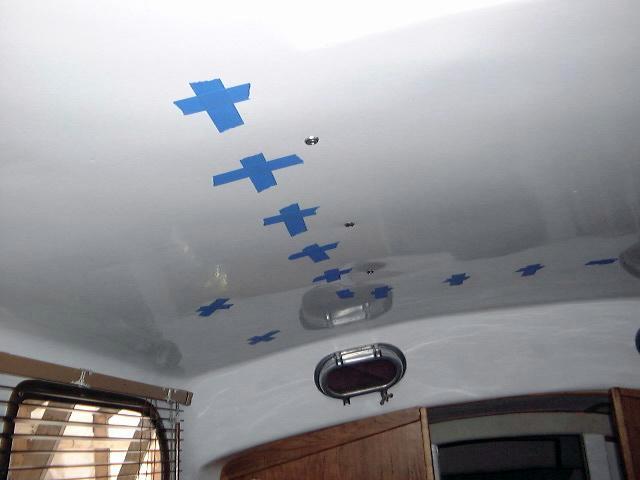
 With
the final fitting and installation of our new dodger
pending, it was time to install the coamings for good. The first step was
to fit them in place and drive one of the center screws mostly in, to bend the
coaming into place temporarily. This was so I could mark the outline of
the coaming blocks on the side of the cabin trunk. After marking the
lines, I removed the coaming again and masked off around the lines where the
coaming blocks had been, and also masked the blocks themselves. This is to
make cleanup of the sealant easier when they are installed. Next, I
drilled two holes through the cabin trunk for some stainless screws that will
secure the forward end of the coamings and the blocks. When both sides
were done, I applied some silicone sealant (I want to be able to remove the
coamings for maintenance) to the area around the coaming blocks and at each
screw hole along the length of the coaming. With
the final fitting and installation of our new dodger
pending, it was time to install the coamings for good. The first step was
to fit them in place and drive one of the center screws mostly in, to bend the
coaming into place temporarily. This was so I could mark the outline of
the coaming blocks on the side of the cabin trunk. After marking the
lines, I removed the coaming again and masked off around the lines where the
coaming blocks had been, and also masked the blocks themselves. This is to
make cleanup of the sealant easier when they are installed. Next, I
drilled two holes through the cabin trunk for some stainless screws that will
secure the forward end of the coamings and the blocks. When both sides
were done, I applied some silicone sealant (I want to be able to remove the
coamings for maintenance) to the area around the coaming blocks and at each
screw hole along the length of the coaming.
HINDSIGHT
NOTE and UPDATE (October 2002): This was a bad, bad idea. I
don't know what I was thinking! Two years later, I went to remove the
coamings for refinishing inside over the winter, and discovered that my innocent
silicone had solidly adhered the coamings to the fiberglass, making removal
nearly impossible. Please click here
to read more about this hassle. Lesson: Do not use silicone, ever,
for anything, period. It's pure evil--it fails when you depend on it, and
sticks tenaciously when you don't want it to. What a fine product! I
don't intend to use any sealant when I reinstall the coamings again.
There's no need.
|
|
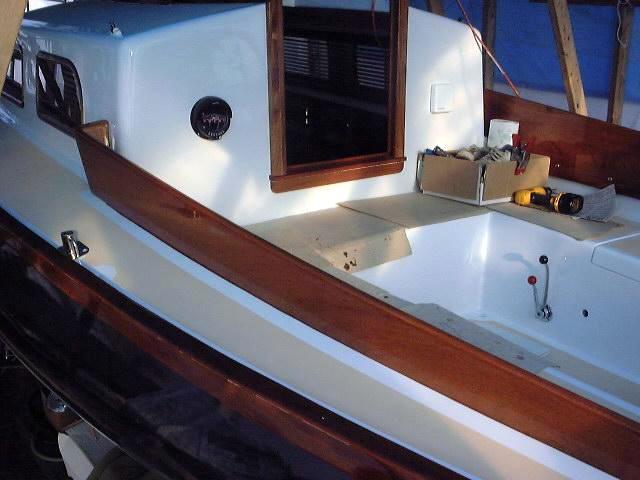
 Then, I installed
the coaming with #12 x 2-1/2" stainless steel screws, as before. When
all eight screws were in place, I went below and drilled (from the inside) into
the coaming blocks for the two screws, and installed them,
with fender washers beneath the finishing washers to spread the load better on
the cabin liner. Then I cleaned up the excess silicone that had squeezed
out. Later, to prevent nuisance water from passing behind the coamings and
into the cockpit, I'll apply a surface bead of silicone along the outside edge. Then, I installed
the coaming with #12 x 2-1/2" stainless steel screws, as before. When
all eight screws were in place, I went below and drilled (from the inside) into
the coaming blocks for the two screws, and installed them,
with fender washers beneath the finishing washers to spread the load better on
the cabin liner. Then I cleaned up the excess silicone that had squeezed
out. Later, to prevent nuisance water from passing behind the coamings and
into the cockpit, I'll apply a surface bead of silicone along the outside edge.
The lighting in the photos is
poor and does not show off the beautiful grain of the mahogany. Later,
when the boat finally sees full sunlight again (yay!) I'll take some more
photos.
|
|
Sea
Hood
I decided to build a sea hood
over the companionway hatch. Not only is this a more waterproof, seaworthy
approach for the companionway, but it will look better too. There are
several ways to construct a sea hood, but I decided to build a simple one out of
mahogany and mahogany plywood. When brightly varnished, this will add an
appreciated touch of extra wood to the boat. (OK, maybe I should buy a
wooden boat next...)
To begin, I first had to
determine how big to make the hood. I got up on the boat with my new
companionway hatch rails and, using them as a rough guide, sketched out a few
basic measurements for the hood--the overall length and width needed. I
also estimated the overall height needed to clear the hatch, taking into account
the thickness of the plywood top (2 layers 1/2" = 1" total). To
maintain the proper clearance inside for the hatch, this measurement had to be
added to the overall height. At the centerline, the finished height was
estimated in this manner to be 4 1/2"; the sides are a little higher, since
they are downhill from the centerline because of the crown of the
coachroof. The inside measurements of the sea hood are: width:
27 1/4"; length: 34"; inside height (clearance): 3
1/2"+. This makes for a nice roomy sea hood, and it covers much of
the broad expanse of the coachroof.
Next, I cut a board for the
forward end of the sea hood, cutting it about an inch higher than necessary at
the center to allow for scribing to the curve. Moving to the boat, I set
the board up in the proper position and leveled it side to side; then, setting
my compass to 1" (the extra width of the board over and above my desired
finished width of 4 1/2") I scribed the line of the coachroof onto the
board and cut it out with a jigsaw. With a couple minor adjustments, the
board fit quite tightly. Now, I could measure for and cut the side pieces,
whose height could not be determined until I had the front piece complete.
The bottom edge of the sides needs to be beveled to match the coachroof curve;
on my boat it was about 4 degrees. With all three boards cut, I had the
basic framework of my sea hood.
|
|
 To
join the pieces together, I cut a 3/8" x 3/8" rabbet in the forward
ends of each side, and in both ends of the forward piece, creating an
interlocking half-lap joint. This minimizes the amount of end grain
showing, provides a pretty strong joint, and is easy and straightforward to
mill. I'm sure dovetails or something would be stronger and look nice, but
I don't do dovetails. I drilled two weep holes on each side of the sea hood,
using a Forstner bit in my drill press to drill the half-circle To
join the pieces together, I cut a 3/8" x 3/8" rabbet in the forward
ends of each side, and in both ends of the forward piece, creating an
interlocking half-lap joint. This minimizes the amount of end grain
showing, provides a pretty strong joint, and is easy and straightforward to
mill. I'm sure dovetails or something would be stronger and look nice, but
I don't do dovetails. I drilled two weep holes on each side of the sea hood,
using a Forstner bit in my drill press to drill the half-circle drains into the side boards. These, while small enough to prevent much
water from coming in except under extreme conditions, will prevent water from
being trapped inside in case any gets in there.
drains into the side boards. These, while small enough to prevent much
water from coming in except under extreme conditions, will prevent water from
being trapped inside in case any gets in there.
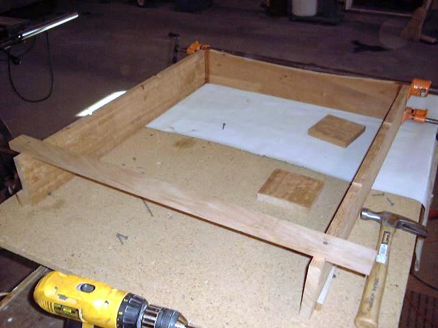
After checking the final
fit, I mixed some epoxy resin with mahogany sawdust in it for color and 406
colloidal silica for strength, cleaned the joints and glued the pieces together,
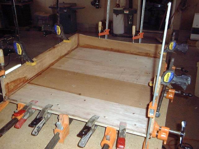
making sure they remained square. I attached a brace to the aft end to
hold it open the right amount, and drive some drywall screw "clamps"
into the bench to wedge the pieces in to the proper position. In the
photo, left, the sea hood is upside down, with the bottom edge facing up.
|
|
The next day, the epoxy had
kicked, so I removed the clamps to continue working on the sea hood. The
next step was to rout a rabbet in the top edge of the three-sided framework to
accept the plywood top. For strength, I planned a two layer laminated
top--structural merranti plywood beneath, and 1/2" mahogany plywood for the
top surface. The rabbet is necessary not only for strength, but also to
hide the edge grain of the plywood. When installed, the plywood will be
flush with the top of the rails.
 The
depth of the rabbet needed was about 15/16" (merranti plywood is measured
in metric units, and is slightly less than 1/2" in thickness). I made
three passes with my router and a 1/2" rabbeting bit; this leaves 1/4"
of the rail at the top, with a 1/2" shelf all around for the plywood to
rest upon. I clamped an extra board to the rails as I routed to give the
router base a little more support than the 1/4" top width would
allow. I checked the final depth carefully on a scrap piece of stock to
make sure that the plywood top would end up perfectly even with, or just
slightly lower than the side of the rail; I didn't want the plywood to stand
proud, since it can't be sanded flush without ruining the veneer. I would
prefer to have to sand the rails down slightly so they are perfectly flush with
the plywood. The
depth of the rabbet needed was about 15/16" (merranti plywood is measured
in metric units, and is slightly less than 1/2" in thickness). I made
three passes with my router and a 1/2" rabbeting bit; this leaves 1/4"
of the rail at the top, with a 1/2" shelf all around for the plywood to
rest upon. I clamped an extra board to the rails as I routed to give the
router base a little more support than the 1/4" top width would
allow. I checked the final depth carefully on a scrap piece of stock to
make sure that the plywood top would end up perfectly even with, or just
slightly lower than the side of the rail; I didn't want the plywood to stand
proud, since it can't be sanded flush without ruining the veneer. I would
prefer to have to sand the rails down slightly so they are perfectly flush with
the plywood.
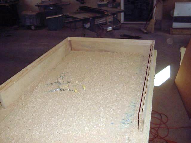
With the rabbet milled, I cut
several pieces of scrap merranti to the proper width; these will form the base
layer. I didn't have a large enough piece to fill the entire area, so I
made do with four scraps, cut precisely to fit. Then, I cut a piece of
mahogany plywood (exterior) to fit on top, being careful that it filled
the space exactly. To attach the plywood, I mixed some epoxy resin with
#406 again for thickness and strength, and added more sawdust to color the
mixture. I thickened the mix so it was about the consistency of
honey or ketchup. I spread a good coat of epoxy on the entire rabbet and up the
sides, and also on the edges of the first layer of plywood. After
installing the four pieces of the first layer, I spread more of the epoxy mix
all over the top surface of the layer, then installed the mahogany plywood on
top. I clamped the sides together, and also ran clamps lengthwise to pull
all the caps closed around the edges.
|
|
 With
everything securely clamped, I turned the assembly carefully over, and then
drove short screws through the bottom, invisible layer of plywood into the
mahogany above to pull them together into the epoxy. I will remove these
screws later when the epoxy is cured. I also added a few clamps here and
there as necessary to pull the plywood tightly into the rabbet. I ended up
with a dozen clamps or more all over the thing...you can never have enough
clamps in the shop! I left the assembly to cure overnight. With
everything securely clamped, I turned the assembly carefully over, and then
drove short screws through the bottom, invisible layer of plywood into the
mahogany above to pull them together into the epoxy. I will remove these
screws later when the epoxy is cured. I also added a few clamps here and
there as necessary to pull the plywood tightly into the rabbet. I ended up
with a dozen clamps or more all over the thing...you can never have enough
clamps in the shop! I left the assembly to cure overnight.
The next day, I removed the
clamps and all the screws, and then sanded the entire piece, taking care not to
go through the veneer--although in a couple places at one corner I unfortunately
went through despite my best efforts. It's barely noticeable, and I don't think
I really could have avoided doing it under the circumstances, but it was just
what I had been trying to avoid! When I had done a rough sanding, I
rounded the top corners and forward vertical edges with a 1/4" roundover
bit in my router, and then switched to my palm sander for a quick sanding with
120 grit. Next, I turned my attention to the aft end of the hood, the open
end facing the cockpit. I needed to cut a piece of trip to cover the
exposed end grain of the plywood top and also to cover a little bit of veneer
chipping that had occurred when I crosscut the plywood to size.
|
|
To do this, I milled a simple
overlapping piece of trip that covers the entire 1" thickness of the
plywood, and overlaps the top by 1/4", neatly giving the edge a nice
finished look. I rounded the top edges and prepared to install it with
epoxy, after first cutting two small strips to cover the end grain of the side
pieces and to make these flush with the new trim piece. I clamped the
pieces in place to sit overnight.
 After letting the epoxy cure, I
sanded the entire piece to remove any excess epoxy and to prepare the surface
for varnishing. I also sanded the interior surfaces, to which I applied a
coat of Brightside primer in preparation for two coats of Brightside. After letting the epoxy cure, I
sanded the entire piece to remove any excess epoxy and to prepare the surface
for varnishing. I also sanded the interior surfaces, to which I applied a
coat of Brightside primer in preparation for two coats of Brightside.
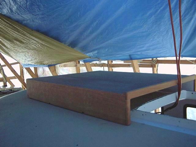
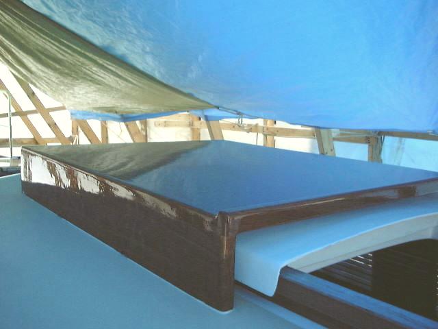
I temporarily installed (placed)
the sea hood on the boat to allow for the dodger measurement; I will remove it
and complete the finishing process before installing it permanently with caulk
and screws from beneath. There's just a little fine tuning necessary on
the curve at the forward end, which I can quickly accomplish with a sander.
|
|
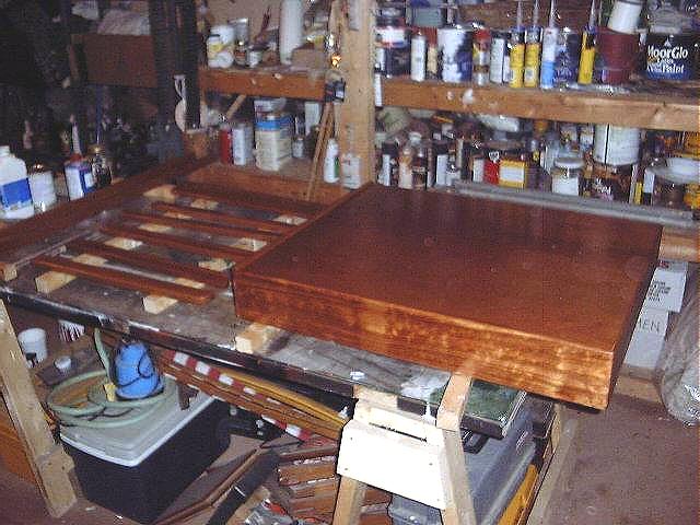 I began the long process of applying 10 coats
of varnish to the sea hood. As with the other brightwork on board, I am
using Epifanes gloss as follows: first coat thinned 50%; second coat
thinned 25"; third coat thinned 15%; subsequent coats thinned only as
necessary for proper flow and leveling, usually about 5% or less. When the
trim is completely varnished, probably in about 3 weeks, I will install it on
the boat as soon as temperature allows the use of sealant. Of course, I'll
have to install the sliding hatch first. I began the long process of applying 10 coats
of varnish to the sea hood. As with the other brightwork on board, I am
using Epifanes gloss as follows: first coat thinned 50%; second coat
thinned 25"; third coat thinned 15%; subsequent coats thinned only as
necessary for proper flow and leveling, usually about 5% or less. When the
trim is completely varnished, probably in about 3 weeks, I will install it on
the boat as soon as temperature allows the use of sealant. Of course, I'll
have to install the sliding hatch first.
|
|
 After
installing the sliding
hatch and rails, I turned to the final installation of the sea hood.
This was a matter of proper positioning, followed by marking the After
installing the sliding
hatch and rails, I turned to the final installation of the sea hood.
This was a matter of proper positioning, followed by marking the  outlines
on the deck, drilling oversized 3/8" holes for some screws that pass up
through the cabin, filling the holes with thickened epoxy and letting it cure.
To prevent the epoxy from drooling into the cabin, I taped over the holes from
the inside. outlines
on the deck, drilling oversized 3/8" holes for some screws that pass up
through the cabin, filling the holes with thickened epoxy and letting it cure.
To prevent the epoxy from drooling into the cabin, I taped over the holes from
the inside.
|
|
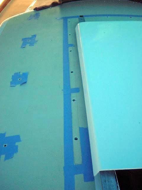
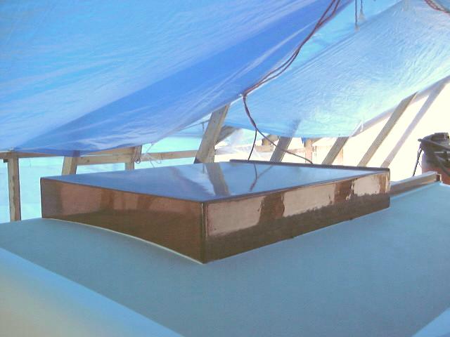
 When the epoxy
cured, I redrilled slightly
smaller holes for the screws, masked off as necessary, laid down a bead of
polysulfide and installed the sea hood with stainless steel screws and finishing
washers from beneath. In the areas where the little drain holes are in the
sea hood, I did not apply any caulk to ensure that they work as designed. When the epoxy
cured, I redrilled slightly
smaller holes for the screws, masked off as necessary, laid down a bead of
polysulfide and installed the sea hood with stainless steel screws and finishing
washers from beneath. In the areas where the little drain holes are in the
sea hood, I did not apply any caulk to ensure that they work as designed.
Sea hood project is complete! The
lighting in these photos is awful; I will post better photos when the boat is
open to the sunlight again.
|
|
|
|
|