|
Battery Charging and Monitoring
This page was last updated
on March 26, 2002.
|
|
One of my pet peeves in past cruises on boats
of all kinds is the lousy electrical systems--that is, the lousy capacity of
such systems. I am always annoyed to have to worry so much about running
the batteries down, sitting in near darkness, and listening to the noisy engine
clatter away while wondering if the batteries are charged yet. I was
determined to have a good house battery system on Glissando, one that
would allow normal amounts of usage over a few days without needing to run the
engine, or with a small input from solar panels or wind generator. Nothing
ruins a pleasant harbor during a cruise more than your own engine chugging away,
or someone else's.
In my research, I learned many things about
batteries, charging systems, and the electrical systems on boats in
general. I have included some sources at the bottom of this page. I realized that the batteries on most of the boats I had spent any
time on had been woefully inadequate and poorly managed by the charging
system. Why, my father's 40-footer had two battery banks with less total
power (amp-hours) than I am planning for Glissando, and much more
electrical equipment to power. I learned how poorly treated most batteries
are during charging, which explains the short life of most boat batteries, not to mention the
constant worry of running them down when anchored overnight while running a few
lights in the cabin. It seems that the basic regulators on most boats tend
to overcharge the batteries, or don't charge fast enough, or the alternators are
simply undersized or even oversized. There's a ton of information
available, and sorting through it all took quite a bit of time and energy. From all this information overload, I gleaned
that the key to successful battery management, charging and usage lies in
proper, multi-step regulation and accurate battery level monitoring--during and
after the charging sequence. Being able to note at a glance the exact
state of the batteries means that they can be charged when, and only when,
necessary, and then charged the proper amount. Of course, this equipment
is an upgrade over a more basic system, but I hope it will be worth the cost and
effort in the long run, especially during longer cruises that we plan.
(OK, so I'm having a little fun, too!)
For more information on design considerations,
charging, regulators, and the setup I am using, please check out the Ample
Power Primer, which contains some good info on these subjects and will
likely explain better than I can.
I decided upon a single house battery bank of
two Trojan T-105 golf cart batteries wired in series for 12 volts, and a single,
separate engine starting battery. This gives the house battery bank a
capacity of 220 amp-hours, which is over four times the project maximum daily burden on the
system. Read more about this on the wiring page. In practice, I think the usage will be
even less. This battery bank also allows future appliance expansion if
desired, without having to add a second or larger battery bank. We may
well install a DC refrigeration system in the future, and the planned battery
bank will allow operation of that system without need for upgrading. Please
visit the battery page for more information on the
batteries selected, their installation, and the theory behind the charging and
maintenance of batteries that makes this charging system make sense...hopefully.
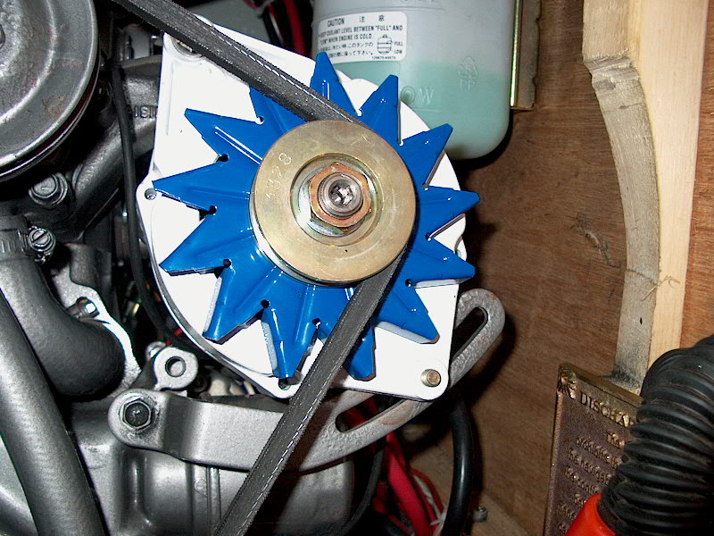
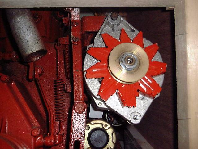 I
purchased a digital battery monitor and three-step regulator, manufactured by
Ample Technology, from Jack Rabbit
Marine. These items, in combination
with a new high output 125-amp Amptech alternator (left), will help manage the charging system efficiently
and effectively. I'll post more on the installation of these items later
when it is complete (see below for a note on the
alternator). Note that the alternator is not fully
installed--I need to modify the wood support you see to the right, to allow the
alternator to swing out more, and I also have to modify the lower bracket to
support the alternator. I
purchased a digital battery monitor and three-step regulator, manufactured by
Ample Technology, from Jack Rabbit
Marine. These items, in combination
with a new high output 125-amp Amptech alternator (left), will help manage the charging system efficiently
and effectively. I'll post more on the installation of these items later
when it is complete (see below for a note on the
alternator). Note that the alternator is not fully
installed--I need to modify the wood support you see to the right, to allow the
alternator to swing out more, and I also have to modify the lower bracket to
support the alternator.
UPDATE!
In June 2002, I replaced the alternator with a smaller one. Even with the
new engine, this monster one was way oversized, and was simply too much strain
on the engine when it was kicked in at maximum charge output. I replaced
it with a Balmar 80 amp alternator that worked very well. Click
here for details.
There are numerous connections to be made
between several components and pieces of hardware in the battery
monitoring/charging system, so the first step was to consider locations for the
various equipment. (Click here
to view a PDF schematic of the system.)
|
|
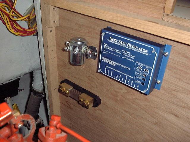
 I
installed the regulator, solenoid, a heavy duty fuse block, positive and negative
distribution terminals in the engine room, trying to place them so that they
would be relatively close to the batteries' proposed location in the cockpit
locker while remaining close to the electrical panel and monitor buses.
The regulator, a shunt, and the solenoid were installed on the port side of the
engine room, while I installed the fuse block and distribution I
installed the regulator, solenoid, a heavy duty fuse block, positive and negative
distribution terminals in the engine room, trying to place them so that they
would be relatively close to the batteries' proposed location in the cockpit
locker while remaining close to the electrical panel and monitor buses.
The regulator, a shunt, and the solenoid were installed on the port side of the
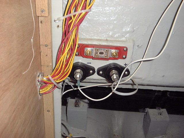
engine room, while I installed the fuse block and distribution  terminals
for the positive and negative distributions on a block attached to the front of the cockpit well inside the engine room.
Other critical components include the alternator, a simple on/off battery
switch, and positive and negative distribution buses that I installed behind the electrical
panel. With these items installed, all the basic pieces are in place, and
I can measure for the connecting wires as needed. terminals
for the positive and negative distributions on a block attached to the front of the cockpit well inside the engine room.
Other critical components include the alternator, a simple on/off battery
switch, and positive and negative distribution buses that I installed behind the electrical
panel. With these items installed, all the basic pieces are in place, and
I can measure for the connecting wires as needed.
The regulator is interwired with the monitor,
alternator, and batteries with a series of wires. A solenoid is also installed
in the system, and the regulator connects the separate starting battery when the
engine is started and the alternator begins producing. When the engine is
shut down, the starting battery is automatically isolated, so there will also be
a fully charged battery available to start the engine. By sensing the charge
state, temperature, and other conditions, the regulator varies the alternator
output to the batteries for the most efficient and proper charge at all times, with
bulk charge periods, absorption charge periods, and final cut off when the
batteries reach the state of full charge. Following the supplied
schematic, I ran wires--mostly #16 AWG, but some #14AWG, as indicated--between
the regulator, monitor, alternator, distribution terminals, and batteries.
The monitor is interconnected in a similar manner to the regulator, batteries,
distributions and a few other connections as indicated on the drawing.
|
|
The other critical part of the charging system
includes heavy cables running between the batteries, distribution, engine
ground, and battery switching solenoid. Most of these cables are indicated
on the drawings as 2/0 size--heavy, stiff, expensive stuff, and miserable to
work with. After a few days' work (on and off), I finally made up the last
connection with the 2/0 cable. There are several more wiring runs that
have to be made, including the positive and negative connections to the
alternator, and the starter wiring; these final connections will be made with #2
AWG cable, which is on order as of this writing. I found Jamestown
Distributors to have the best prices on battery cable and other wiring
accessories. I am working off three or four different drawings, and it
gets a little confusing sometimes. I usually find it's best to just go for
one wire at a time, and things seem to fall into place. Actually, the
challenge is kind of fun, and I like running the wires and organizing everything
for a clean appearance. All wires are connected with ring terminals or, in
the case of the regulator connections, with fully insulated female quick
connects. Wiring to the shunt requires a shielded twisted pair, which I
purchased in a pre-made sheathed cable and connected as necessary. Wiring
for two temperature sensors, which are connected to the battery and then to the
regulator and the monitor, required twisted pairs to reduce interference.
Rather than use the expensive shielded wire I used on the shunt wiring--it was
not specifically called for like it was with the shunt wiring--I
twisted the wires together by chucking one 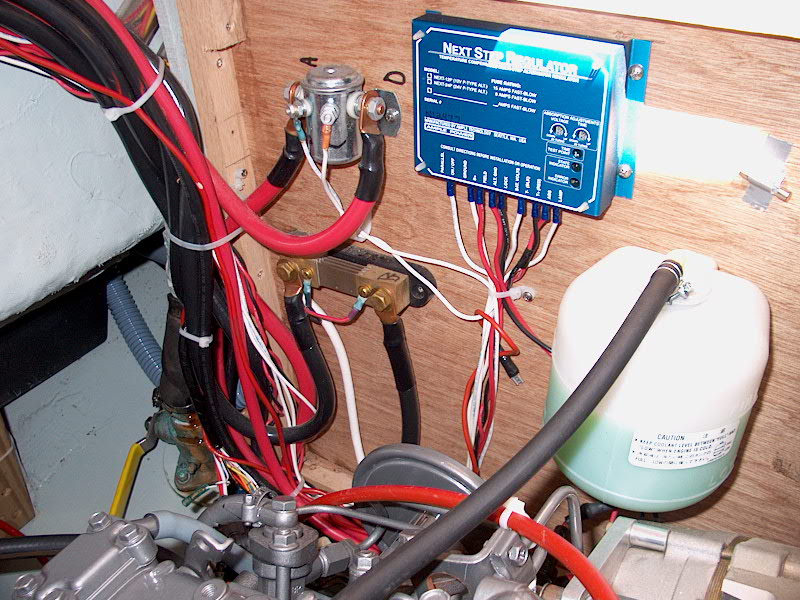 end of each in my drill and , with
someone holding the other ends with a pliers, slowly ran the drill to twist them
together. I taped the wires every few feet to keep then from untwisting
during installation. end of each in my drill and , with
someone holding the other ends with a pliers, slowly ran the drill to twist them
together. I taped the wires every few feet to keep then from untwisting
during installation.
7/17/01: With several months of use
behind us, I can now report on the electrical system and charging. There
have been no problems to date, although I haven't really had a chance to learn
how to use the complex monitor. I can use and view all the basic and
helpful parameters--amp-hours consumed, amp-hours remaining, percent of charge,
total amps draw at any given time, etc. However, I haven't figured out how
to set the system for optimum charging, and haven't really played with it
much. This will all come in time. One thing I need to figure out is
whether the monitor will automatically add amp-hours back in when the system is
being charged, or if I have to reset it to full every time. UPDATE--I
figured it out. The monitor DOES give this information, and is very
slick. The reason I could never figure out before whether it was offering
this information was that the system was never charging. Read on.
|
|
UPDATE!
8/13/01
A week after installing our new engine, we
headed out for a brief cruise. On the second day of the cruise, I
discovered that the batteries were very low--I couldn't start the engine without
using the emergency parallel switch. Now, I had had questions about the
charging setup since the beginning, but never really had a chance to sort it out
because I was doing so much work to the old engine. Now, it didn't seem to
be charging. Why?
After a couple moments of minor despair, and
disappointment, I was galvanized into action. I had planned to spend some
time during the cruise working on the charging system anyway, so I had with me a
printed troubleshooting guide that I found from the Ample Power website.
Reading through, I was immediately struck by one of the early paragraphs:
"When the system fails to charge,
the ignition switch is a good place to start looking. You don't need to look
at the switch itself, but you do need to see that the alternator regulator is
getting voltage when the switch is on. That is, find an input to the
alternator regulator that shows battery voltage when the ignition switch is
on, and no battery voltage when the switch is off."
I quickly realized that I had never wired the
power (on-off) terminal on the regulator, even with the old engine. The
reason I neglected this was that I wired the bulk of the electrical system in
March 2001, and had not yet installed an ignition switch or instrument
panel. Then, with the engine in a non-running condition for much of the
early part of the season, it never made its absence apparent. By August, I
had finally used enough battery power to make starting difficult--since the
batteries had never been charged all season!
I found a length of wire in my electrical kit,
and promptly wired up the regulator to the ignition switch. This
only took a few minutes. Now, when the switch turned on, there was power
to the regulator--there's a series of lights that are supposed to light, and
they did. I started the engine, and checked the regulator--the status
light was blinking a code, which, from reading the manual, I decided meant that
it was charging as designed. The energy monitor also indicated the volts
and amps that were being replaced into the house and starting batteries. Hooray!
This was a simple fix, but I admit that at the beginning, I had no idea how to
proceed. Diagnosing electrical gremlins is not necessarily my strongest
point. However, with the help of a good troubleshooting guide--and, more
importantly, the wiring diagram for the regulator--it was easy to figure out.
Of course, one thing often leads to
another! We happened to motor all the way to our next destination that
day, and when I shut down the engine, I noticed that the alarm (oil pressure and
water temperature) build into the Yanmar B-panel did not sound before I turned
the key off. Normally, this alarm sounds whenever the key switch is on and
the engine not running. But this time, I did not hear it. This
seemed strange, but it wasn't till later that I really understood that there was
a problem. Later in the afternoon, I thought I'd look into it a little
more. First, I satisfied myself that all the basics were in place--the
wiring harness was plugged in, there were no loose connections, etc. I
then decided that I had a real problem on my hands--no power to any part of the
panel, which meant no starting the engine. Why? I spent some time
looking over the system, and reading the wiring diagram for the panel and
harness in my service manual. Nothing jumped at me, and, since we were
staying put the next day, I decided to wait till the morning for a fresh
outlook.
Of course, the next morning, I immediately
noticed the fuse on the wiring diagram: a 30-amp fuse in the main power
supply to the panel. Despite my suspicions yesterday that it must be
something dumb like a blown fuse, I couldn't find a fuse on the diagram...I must
have been tired. It took me a short time to open the fuse holder and
confirm that, yes, the fuse was blown. I replaced it, and the panel and
alarm worked. I started the engine and ran it for a while, hoping to
figure out how and when the fuse had blown. When I shut down, I caught a
split second of the alarm tone before it quit--the fuse had blown again, but
this time I had isolated when it happened. For some reason, there was
additional power surging through that line at the moment the engine shut down,
which blew the fuse. I wasn't sure why, but it only started after I had
hooked up that regulator wire, so I disconnected it again for the time
being. Now I have to figure out why this is happening, and what to do to
fix the problem.
UPDATE--8/29/01
Troubleshooting the silly fuse brought to
light another, far more serious problem. After the cruise, I determined to
figure out what was causing the fuse to blow. During one session on board,
I was playing around with things a bit. One concern I had had throughout
the entire engine repower was where the spade connectors in the wiring harness
were supposed to connect to the new alternator. The Hitachi alternator
that came with the engine is internally regulated, and the terminals on the back
are different than the ones on my AmpTech alternator that is an integral part of
my electrical system. I studied the wiring diagrams and everything I could
find, and figured that the terminals were just named differently, so I connected
the wires to the field and stator terminals on my alternator. This is how
it was connected during the cruise, and there didn't seem to be any
problem--except that the charging idiot light on the panel was always lit.
Thinking that maybe I had these two wires backwards on the terminals, I switched
them. Running the engine, for some reason this did not seem right, so I
switched them back and decided, just before I was planning to head in for the
day, to run the engine with the regulator hooked up again--it had been unhooked
since the cruise. I started the engine and ran it for a couple minutes,
then shut it down--I wanted to see if that fuse was blowing on shutdown, as I
had earlier surmised. Smelling a strange smell right after shutdown, I
opened the cockpit locker to check out the battery--I didn't know if there was
maybe a problem there. There was some unusual-smelling smoke coming out of
the locker, and I couldn't identify the smell right off. It didn't really
seem electrical in nature, but what else could it be? I thought that maybe
the engine had blown a little exhaust smoke of something out of the air intake
when I shut down. Puzzled, I put the boat to bed and went home to mull
things over a bit.
The next day, I returned and tried things
again. Now wary of the previous day's smoke, I was prepared for anything
when I turned the key and started the engine. Almost immediately, the
smoke began, and I quickly traced it to the engine wiring harness extension--the
part that runs between the engine and the panel. It was smoking up a
storm, and the unusual smell was the electrical tape that the whole thing is
wrapped with--melting. Yikes! What was this?
 After
shutting down the engine, I inspected the harness while it was in place.
It was toast, or at least appeared to be. I removed the harness extension
and noticed that a shorter harness, at the panel end, was also in trouble.
I removed that, and also the panel, because I could see heat damage on one of
the wires there also. I figured that my dumb switching of the wires the
day before had caused the damage--and therefore assumed that, by switching them
back, all would be well, so I drove up to Orr's Island for a new harness.
(They don't give these things away...) I described what had happened to
Bill, the owner, including the fuse problem, in the hopes that maybe he could
shed some light on what might had happened. But I couldn't get any real
answers on the alternator terminals from him, except to find out ( in general
terms) that the terminals were not the same. He was in a rush to have his
lunch. I also got the impression that he kind of thought larger
alternators and smart regulation were unnecessary and kind of stupid, so I
didn't really see getting any more beneficial assistance there. Feeling a
little chastised and defeated I left, clutching my pricey harness, and spent the
drive home trying to figure out why this might have happened. After
shutting down the engine, I inspected the harness while it was in place.
It was toast, or at least appeared to be. I removed the harness extension
and noticed that a shorter harness, at the panel end, was also in trouble.
I removed that, and also the panel, because I could see heat damage on one of
the wires there also. I figured that my dumb switching of the wires the
day before had caused the damage--and therefore assumed that, by switching them
back, all would be well, so I drove up to Orr's Island for a new harness.
(They don't give these things away...) I described what had happened to
Bill, the owner, including the fuse problem, in the hopes that maybe he could
shed some light on what might had happened. But I couldn't get any real
answers on the alternator terminals from him, except to find out ( in general
terms) that the terminals were not the same. He was in a rush to have his
lunch. I also got the impression that he kind of thought larger
alternators and smart regulation were unnecessary and kind of stupid, so I
didn't really see getting any more beneficial assistance there. Feeling a
little chastised and defeated I left, clutching my pricey harness, and spent the
drive home trying to figure out why this might have happened.
|
|
 The
next day, I spent some more time inspecting the original harness and the back of
the panel. It appeared to be only one wire that had gotten hot. On
the panel, I had to spend some time replacing this wire where it was damaged,
because otherwise it might have meant that I would need a whole new panel in
order to replace this one wire, because of the widespread damage. It's a
little hard to explain why, but the wiring behind the panel is complicated, and
this particular wire split into about 100 directions, so I was legitimately
worried that it couldn't be replaced. However, I was able to figure out a
way, including replacing the little itty-bitty teeny-weenie metal connector
inside the harness plug. The
next day, I spent some more time inspecting the original harness and the back of
the panel. It appeared to be only one wire that had gotten hot. On
the panel, I had to spend some time replacing this wire where it was damaged,
because otherwise it might have meant that I would need a whole new panel in
order to replace this one wire, because of the widespread damage. It's a
little hard to explain why, but the wiring behind the panel is complicated, and
this particular wire split into about 100 directions, so I was legitimately
worried that it couldn't be replaced. However, I was able to figure out a
way, including replacing the little itty-bitty teeny-weenie metal connector
inside the harness plug.
By the way, the wire in question that was
destroyed is a small wire that, according to the wiring diagrams, is supposed to
be the hot lead for the idiot lights and such on the panel. The diagram
calls for it to run from the "exciter" terminal on the Hitachi
internally-regulated alternator back to the panel, where it splits several
ways. I started wondering exactly what function that wire had...there was
more information needed, but I knew (obviously) that something wasn't right.
I replaced the wiring harness in the boat and,
leaving the regulator unplugged for now, tried everything out. No
problems. However, I was feeling a little over my head now, so I decided
I'd better check over all the wiring in the charging system to make sure it was
wired correctly before frying another harness up. Not being an expert at
the tedious chore of troubleshooting wiring, I called upon my friend
Smitty to come have a look with me.
On the chosen day, I explained all my problems
to him, and, after a bit of time, he was able--amazingly, to me--to isolate the
issue that seemed to be causing the 30-amp fuse to blow. It seems that the
heat shrink on the terminal end of the hot lead to the panel key switch--the
wire that contained the fuse--had a small hole in it, and the metal terminal was
bearing directly on the starter hot terminal. I still don't know how he
managed to find this. It was barely noticeable. He redid this
connection, and we started the engine up--with regulator connected. He
hadn't been able to find anything wrong with the associated wiring.
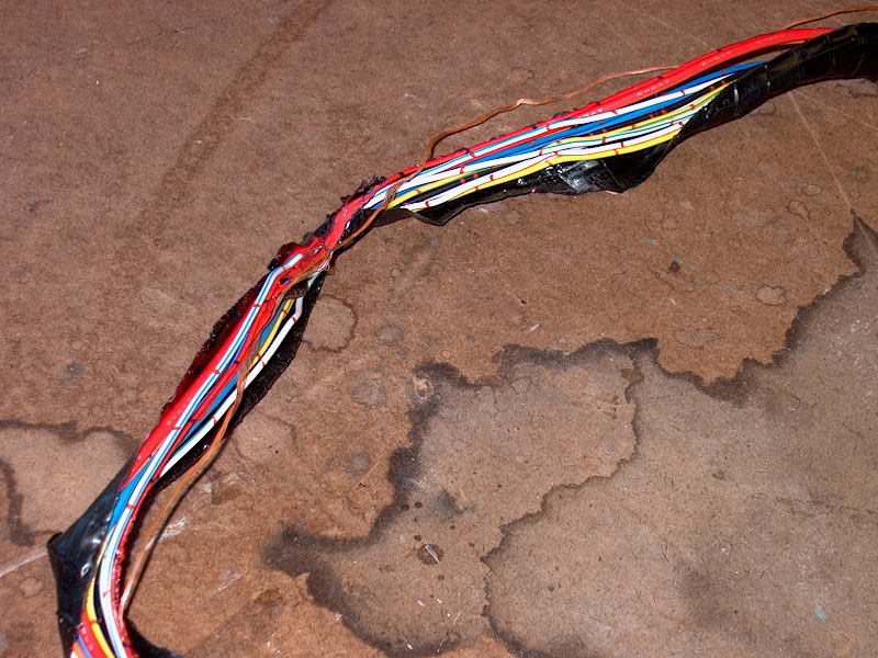
We were standing in the cockpit with the
engine running, feeling smart and smug...when I noticed that strange smell
again. I knew what that meant, and flung open the cockpit locker where the
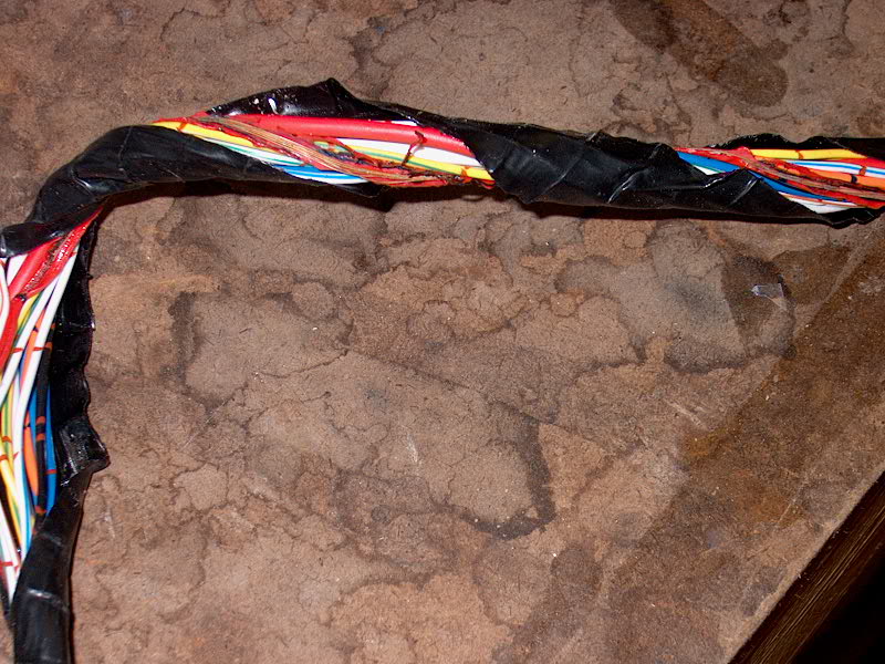
harness was run. Smoking again! I shut the engine right down, but
the damage was done--and even worse than the first time. There were long
lengths of the wire that were completely stripped of insulation, and the
associated heat had damaged the nearby wires in the harness as well.
Wonderful. So what was causing this? I was glad Smitty was
there. He immediately set to task trying to figure out what had
happened. It was the same wire as before--that little hot lead.
Obviously, way, way too much current was running through this tiny wire.
But why?
After a time, Smitty figured out the problem,
seemingly. This wire was the one that connected to the back of the
alternator, on one of the spade terminals. Obviously, these terminals are
incompatible with the ones on the original alternator. The wire was
connected to the stator terminal, and, lacking the internal regulation, it was
obviously trying to channel the full charging force of the alternator through
this wire. Also, the wire is kind of a roundabout loop--there is power
supply to the panel through the ignition switch that also feeds the hot leads
for the idiot lights and alarm. This was creating a very significant
overcurrent through the line. I think that perhaps this loop is supposed
to exist in the as-designed wiring to show that the system is properly charging;
with the external regulation and separate battery monitor, not only is this
unnecessary, but dangerous. Too bad it took two wiring harnesses to figure
this out! We determined that this wire was unnecessary, and should be
disconnected from the alternator entirely.
The harness was too fried to try the engine
again to support our new theory, so we went in. I ordered another
harness--this time online from Torresen Marine, since I couldn't face Orr's
Island again! However, a couple days later--with a fresh outlook--I
inspected the first wiring harness that I fried, and noted that it looked like
all the other wires contained therein appeared to be undamaged. I took it
out to the boat with me, intending to put it aside in storage for someday when I
would remove the burned wire--I was planning to wait for the delivery of my
second brand-new harness in another day or so, when I would install it.
However, when I got to the boat, I decided to have a go at repairing the
original harness, and spent some time removing all the old tape wrappings,
removing the offending wire and inspecting the remaining ones. They
seemed to be OK, so I reaped the harness--minus one wire--and installed it for a
test. I had already removed the terminal from the back of the alternator
and taped it up.
Success! The panel worked correctly, and
the alarm and idiot lights worked as designed when I turned the key.
Feeling bold, and thinking that we had identified and licked the problem, I
hooked up the regulator and started the engine. Everything worked
perfectly--the system charged, the harness didn't burn up, and the panel worked
correctly. I ran the engine for about a half hour, with no problems to
report. When I shut down, the fuse didn't even blow. I was so happy
that I went ahead and permanently installed the repaired harness, rather than
wait another day or so for the new one.
The large alternator charges so
fast that there are many times when we really don't need to waste engine power
driving the alternator. Therefore, I decided to install a switch that
would turn the regulator on or off as desired. Click here
to read about it.
Another reason to install the
regulator switch was because the huge alternator really put a strain on the
engine when it was charging--too much strain, as far as I was concerned.
The performance of the alternator really inhibited the engine from operating
normally. I should have known...but I had told the folks at JRM Systems
what type of engine I had, and, not really knowing any better at the time,
didn't question the alternator they sent me.
The regulator switch worked fine,
but in the end I decided it was dumb to have to throw a switch to charge
batteries. Rather than put up with a too-powerful alternator (which worked
very well otherwise), I decided to bite the bullet and replace the alternator
with a more appropriate one--a Bamar 90-75 (75 amp output).
|
|
 Installation
was pretty straightforward--disconnect the batteries, unhook the wires from the
back of the existing alternator, and remove it. Then, install the new
alternator (same case size as the Amptech), hook up the wires (I had to change
three of the ends for the ground wires, since the alternator ground stud was a
larger diameter), and reconnect the batteries. Success! In addition,
the engine belt fits the new alternator pulley better...the old one was not a
perfect fit. The new alternator is perfect. The increase in power (of the
engine) over the old alternator is dramatic, so I will run the engine with the
alternator/regulator connected at all times. The switch is still there
should I need it, though. The new alternator whines more when putting out
(there's a politically-incorrect joke there somewhere), but that's OK. It
pumps out between 30 and 40 Ah of juice when the engine is running only
1200-1500 RPM, and goes up from there. Installation
was pretty straightforward--disconnect the batteries, unhook the wires from the
back of the existing alternator, and remove it. Then, install the new
alternator (same case size as the Amptech), hook up the wires (I had to change
three of the ends for the ground wires, since the alternator ground stud was a
larger diameter), and reconnect the batteries. Success! In addition,
the engine belt fits the new alternator pulley better...the old one was not a
perfect fit. The new alternator is perfect. The increase in power (of the
engine) over the old alternator is dramatic, so I will run the engine with the
alternator/regulator connected at all times. The switch is still there
should I need it, though. The new alternator whines more when putting out
(there's a politically-incorrect joke there somewhere), but that's OK. It
pumps out between 30 and 40 Ah of juice when the engine is running only
1200-1500 RPM, and goes up from there.
I'll keep the Amptech as a very
nice spare.
|
|
Electrical System Information Resources
-
Ample
Power Co.
-
Jack
Rabbit Marine
-
Powertap
-
System
E-Next Schematic
(PDF File)
-
Wiring 12 Volts for Ample Power, by
David Smead and Ruth Ishihara
-
Living on 12 Volts With Ample Power,
by David Smead and Ruth Ishihara
-
Sailboat Electrics Simplified, by
Don Casey
-
Boatowner's Illustrated Handbook of
Wiring, by Charlie Wing
-
Boatowner's Electrical and Mechanical
Manual, by Nigel Calder
|
|