|
A New Mahogany Tiller
This page was last updated
on 1 December 2003.
Click here to
jump to the newest update (July 2004) |
|
When the boat that was to become
Glissando entered our lives, she was equipped with what appeared to
be the original tiller: solid oak, relatively short, and
uninspired. I never intended to use the old tiller, and replaced
it with a store-bought tiller before launching in May 2001. It was
a quick and easy way to get a workable tiller.
The store-bought version
wasn't a perfect fit, but it was longer, higher, and more substantial
than the original oak tiller. Laminated of strips of mahogany and
ash, it was OK looking. You've all seen these things
everywhere. In general, I liked the shape and function of it, but
there was room for improvement.
Then, during the summer
of 2003, the tiller developed a bad split down the longitudinal
centerline, starting at the screwholes securing the tiller
extension. I repaired it
temporarily by wrapping fiberglass cloth around it, which was enough to
get through the remains of the season, but the handwriting was on the
wall: time for a new tiller.
|
|
With the old tiller removed, I began the
templating process in order to build a new tiller. I wanted a
somewhat different shape than the existing--a tiller that came out of
the tiller head more horizontal in attitude, but then curved up steeply
to the ultimate height before continuing forward. This design, at
least in my head, seemed to solve some clearance and use problems that
occurred with the old, basic-arch design, and would provide a horizontal
section at the end where the hand typically grips.
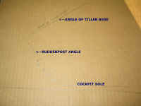 To
begin, I drew a basic mockup of the cockpit sole, rudderpost, and tiller
angle, using a bevel gauge to imitate the actual angles on the boat and
transferring the measurements to a sheet of cardboard I had lying
around. Then, using the old tiller as a sort of guideline, I drew
up a voluptuous new shape on the cardboard, using a flexible plastic
spline and architect's ducks. I cut the new tiller template out of
the cardboard, and "installed" it in the tiller head to see
how it worked in the cockpit. To
begin, I drew a basic mockup of the cockpit sole, rudderpost, and tiller
angle, using a bevel gauge to imitate the actual angles on the boat and
transferring the measurements to a sheet of cardboard I had lying
around. Then, using the old tiller as a sort of guideline, I drew
up a voluptuous new shape on the cardboard, using a flexible plastic
spline and architect's ducks. I cut the new tiller template out of
the cardboard, and "installed" it in the tiller head to see
how it worked in the cockpit.
|
|
|
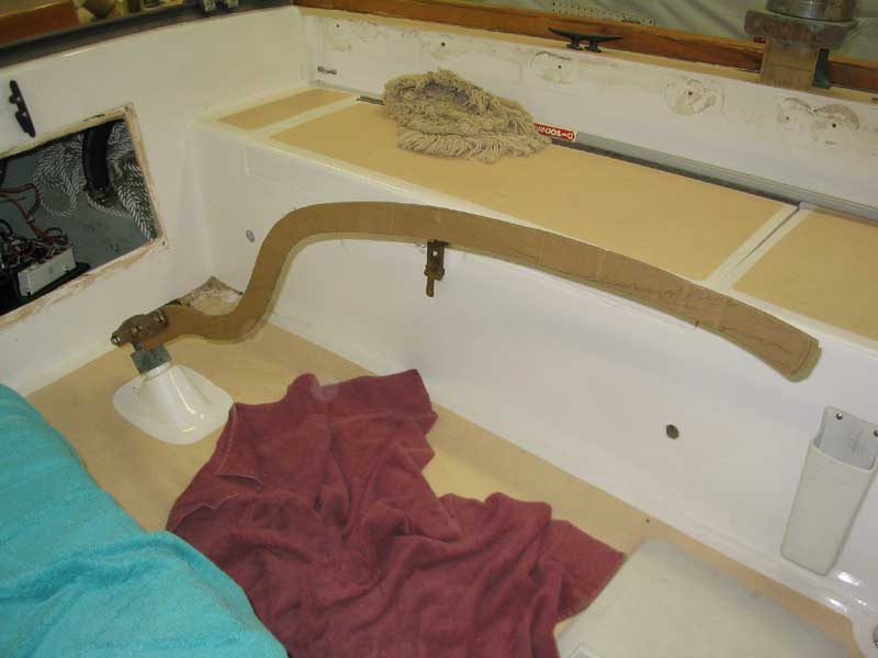
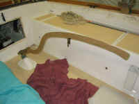 Despite
the floppy cardboard, I could get a sense of the new shape, and saw that
there was a need for a few changes. The forward part of the
template drooped down farther than I liked, and the after portion, above
the "S" curve, was also a bit lower than I had hoped.
But the arch seemed generally OK, though the curve was severe, and the
tiller cleared the seats easily when turned, without even needing to
lift the tiller at all. Despite
the floppy cardboard, I could get a sense of the new shape, and saw that
there was a need for a few changes. The forward part of the
template drooped down farther than I liked, and the after portion, above
the "S" curve, was also a bit lower than I had hoped.
But the arch seemed generally OK, though the curve was severe, and the
tiller cleared the seats easily when turned, without even needing to
lift the tiller at all. |
|
 With
version one in the bag, I decided to refine the general design and
address the minor changes needed. Instead of cardboard, I used a
sheet of 1/4" lauan plywood to create a new template, making a few
modifications to the shape of the original cardboard template. I
decided I wanted the overall height of the tiller end to remain about
the same as the existing tiller (which is about 24" above the
cockpit sole), so that meant raising the end (according to the cardboard
template) by a couple inches. I cut the new template out with a
jigsaw, and tried it out in the cockpit. With
version one in the bag, I decided to refine the general design and
address the minor changes needed. Instead of cardboard, I used a
sheet of 1/4" lauan plywood to create a new template, making a few
modifications to the shape of the original cardboard template. I
decided I wanted the overall height of the tiller end to remain about
the same as the existing tiller (which is about 24" above the
cockpit sole), so that meant raising the end (according to the cardboard
template) by a couple inches. I cut the new template out with a
jigsaw, and tried it out in the cockpit.
|
|
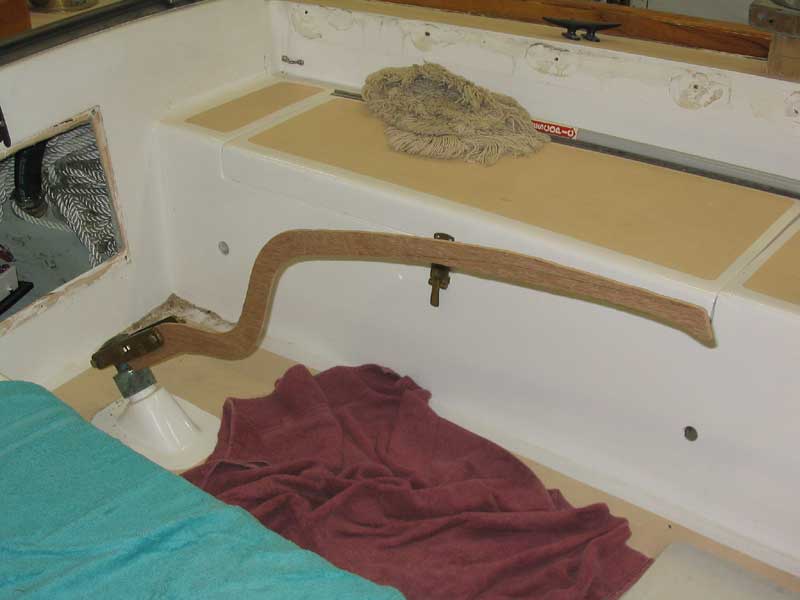
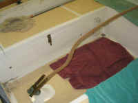 The
lines and curves were a bit unfair, and the overall shape definitely
needed some refining, but this was much more of the shape I had been
envisioning all along. It looks a little funny and awkward as it
stands, since the tiller really doesn't follow a smooth line out of the
tiller head. Obviously, any final version will be much more
refined and will hopefully flow more smoothly. For the time being,
the point is to test basic shapes and designs, with refinement to come
once a final candidate is chosen. The
lines and curves were a bit unfair, and the overall shape definitely
needed some refining, but this was much more of the shape I had been
envisioning all along. It looks a little funny and awkward as it
stands, since the tiller really doesn't follow a smooth line out of the
tiller head. Obviously, any final version will be much more
refined and will hopefully flow more smoothly. For the time being,
the point is to test basic shapes and designs, with refinement to come
once a final candidate is chosen.
|
|
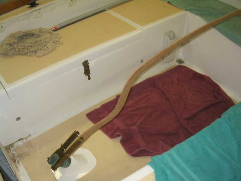
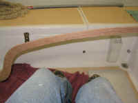 I
tested the new design out and was pleased to see that it cleared my
knees when I sat in a variety of locations, and, as with the original
cardboard template, cleared the cockpit seats nicely. These were
two of the main objectives for the new design. It was also at a
comfortable height for straddling while standing, which I like to do
when powering, or sailing downwind (or upwind in light airs sometimes). I
tested the new design out and was pleased to see that it cleared my
knees when I sat in a variety of locations, and, as with the original
cardboard template, cleared the cockpit seats nicely. These were
two of the main objectives for the new design. It was also at a
comfortable height for straddling while standing, which I like to do
when powering, or sailing downwind (or upwind in light airs sometimes).
|
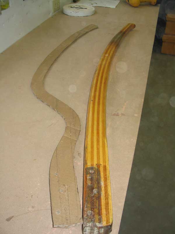
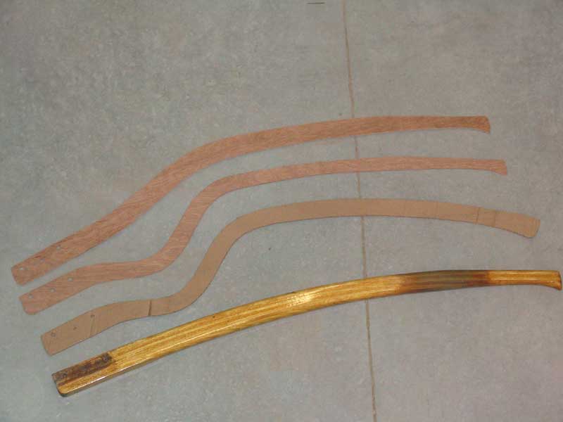
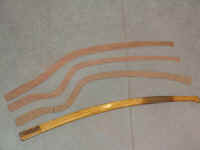
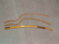 This
picture shows the evolution of the current design...though this design
is not yet cast in stone, or even close to. Starting with the
existing tiller, the major change to the cardboard template is obvious,
with its radically different shape and philosophy. The
evolutionary changes from the cardboard to the lauan template are also
apparent. Note that the three shapes shown here aren't necessarily
properly angled according to how the rudderpost exits the cockpit, so
please forgive any slight inconsistencies in their appearance or apparent
shape. The lauan template at the top of the photo actually sits
the same height above the cockpit sole at its forward (handle) end as
the original tiller at the bottom, and extends about as far
forward. It's just the way in which it reaches that height and
length that is different. This
picture shows the evolution of the current design...though this design
is not yet cast in stone, or even close to. Starting with the
existing tiller, the major change to the cardboard template is obvious,
with its radically different shape and philosophy. The
evolutionary changes from the cardboard to the lauan template are also
apparent. Note that the three shapes shown here aren't necessarily
properly angled according to how the rudderpost exits the cockpit, so
please forgive any slight inconsistencies in their appearance or apparent
shape. The lauan template at the top of the photo actually sits
the same height above the cockpit sole at its forward (handle) end as
the original tiller at the bottom, and extends about as far
forward. It's just the way in which it reaches that height and
length that is different. |
|
 After
a few days' reflection, and some discussion with Nathan (Dasein 668),
who also wanted a new tiller, I decided some modification was in
order. The funky new shape, while close to the ultimate goal, just
lacked the proper aesthetic flow. The solution was to more closely
emulate my existing tiller's shape near the butt end, and to smoothly
merge that shape with the new templated shape, eliminating some of the abrupt
bend in the template that simply didn't look good. The upper
portion of the curve remained in the same place, allowing for excellent
knee and cockpit seat clearance (one of the significant design goals),
but sacrificed a small amount of the lowness of the butt end in favor of
improved aesthetics--and, as I was soon to discover, improved
possibility of successful construction. After
a few days' reflection, and some discussion with Nathan (Dasein 668),
who also wanted a new tiller, I decided some modification was in
order. The funky new shape, while close to the ultimate goal, just
lacked the proper aesthetic flow. The solution was to more closely
emulate my existing tiller's shape near the butt end, and to smoothly
merge that shape with the new templated shape, eliminating some of the abrupt
bend in the template that simply didn't look good. The upper
portion of the curve remained in the same place, allowing for excellent
knee and cockpit seat clearance (one of the significant design goals),
but sacrificed a small amount of the lowness of the butt end in favor of
improved aesthetics--and, as I was soon to discover, improved
possibility of successful construction.
|
|
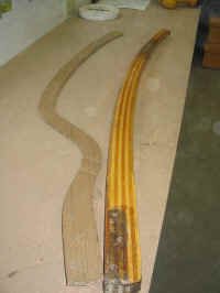
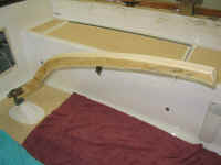 Satisfied
with the lauan template of the new shape, I decided to build a more
full-sized mockup with which I could actually test the operation of the
new tiller. From a scrap piece of 2x10 lumber, I jigsawed the
tiller template, and installed it to the bronze tiller head for a
test. Both of us were pleased with the looks and performance of
the new shape, so we agreed to go ahead with its construction. Satisfied
with the lauan template of the new shape, I decided to build a more
full-sized mockup with which I could actually test the operation of the
new tiller. From a scrap piece of 2x10 lumber, I jigsawed the
tiller template, and installed it to the bronze tiller head for a
test. Both of us were pleased with the looks and performance of
the new shape, so we agreed to go ahead with its construction.
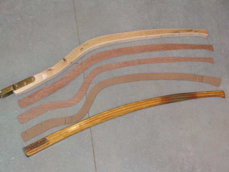
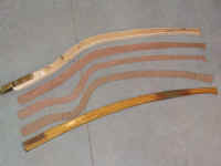
The photo below shows the
full evolution of the tiller shape, from the existing (and generally
satisfactory) stock tiller to the ultimate shape of the new design. |
|
|
|
I planned to make the new tillers out laminated strips of mahogany,
deciding against adding contrasting strips as is common in stock
tillers. I cut enough 1/4" thick strips for the job from a
large piece of 8/4 mahogany that I had on hand, a piece with excellent
color and overall quality, and prepared to build a laminating jig with
which to glue up the tillers.
Presently, though, I had
a problem. It seemed the designed curve was too tight for cold
molding of the mahogany strips. As part of the mold construction,
I used a strip of the mahogany to help me create a fair, smooth curve
between clamping block locations. After I had installed several of
the blocks, I clamped on a piece of the mahogany, but found that I
couldn't make the two-direction bend without splitting the wood. I
wasn't sure if the problem was a factor of the wood simply not being
bendy enough, the jig being too sharp and hard a surface against which
to bend, or a combination of the two. The difficulty arose because
of the requirement for the wood to bend in two directions over a
relatively short span; bending the strips through either of the two
curves would work, but forcing them first into one curve, then almost
immediately into a completely opposite curve, proved to be too
difficult--at least with dry strips.
Discouraged, but far from
beaten, I put the jig and strips aside for a while, and looked into
building a steam box in which to steam the wood strips to make them more
pliable. Steaming the wood was but one possible option; changing
the format of the jig might also work.
Click
here to continue> |
|