|
Small Projects:
Systems
This page was last updated on 26
March 2002.
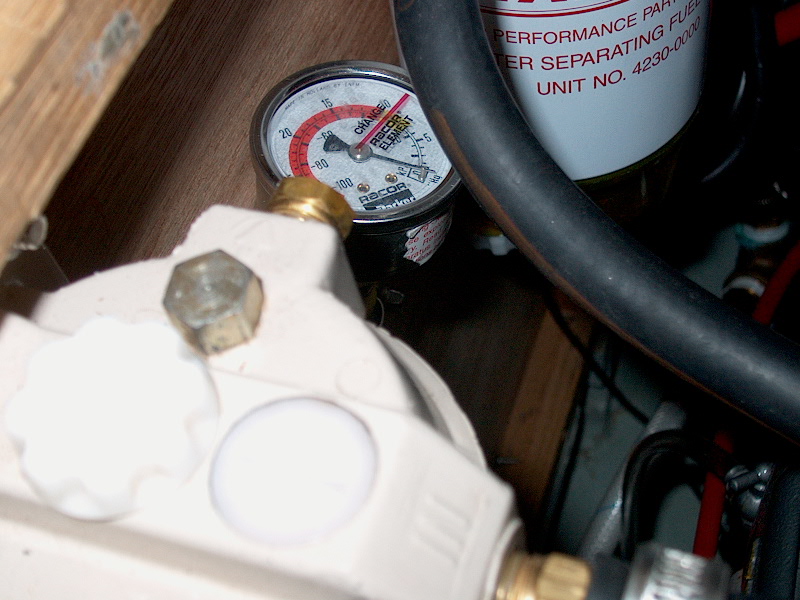
Racor Filter Vacuum
Gauge
This gauge is intended for use to assist in
determining when the fuel filters require replacement. In the most basic
terms, the gauge measures how hard the fuel pump has to suck to move fuel
through the filters. The higher the reading on the gauge, the harder the
pump is working to pull fuel through. When the gauge reaches a
predetermined level of vacuum--the literature indicates 7-10" Hg--the
filter elements require changing. I thought this would make fuel
system maintenance easier and more effective. Rather than changing filters
too often--wasting some of their filtration capacity--or, worse, leaving them
too long before cleaning, this gauge should allow me to tell in an instant what
the filters' condition is.
|
|
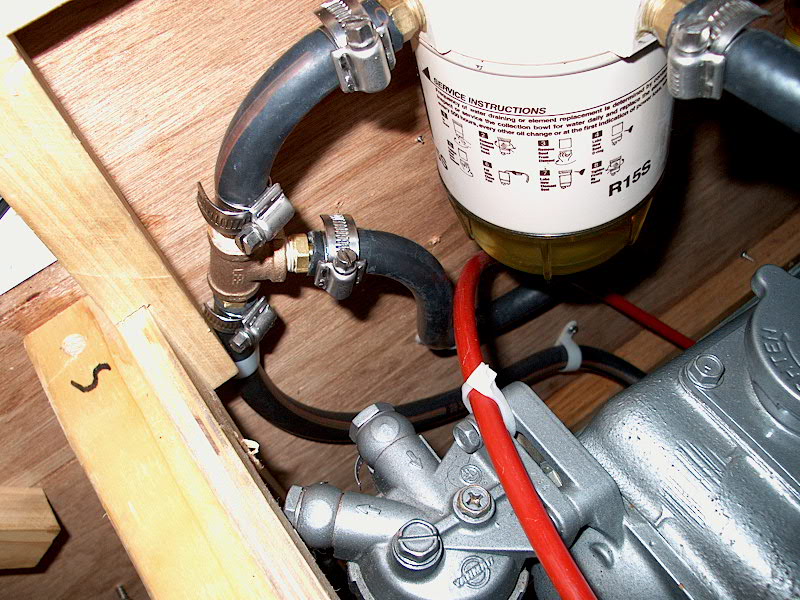
 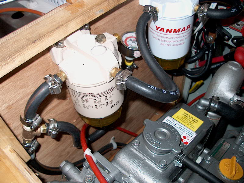 Installation was straightforward. On the
outlet side of my second primary fuel filter, I installed a tee in the fuel line
to the engine. Off the top of the tee, I attached a length of fuel hose
that runs to the Racor vacuum gauge. To keep it out of the way but also
easily visible for inspection, I mounted the gauge between the two primary
filters on the engine room bulkhead. The gauge is intended to be installed
in a panel somewhere, but, not having a suitable location--and not wanting Installation was straightforward. On the
outlet side of my second primary fuel filter, I installed a tee in the fuel line
to the engine. Off the top of the tee, I attached a length of fuel hose
that runs to the Racor vacuum gauge. To keep it out of the way but also
easily visible for inspection, I mounted the gauge between the two primary
filters on the engine room bulkhead. The gauge is intended to be installed
in a panel somewhere, but, not having a suitable location--and not wanting  the
gauge exposed--I elected to just leave it mounted simply in the engine
room. I secured the hose in place with a couple plastic cable clamps,
ensuring that the hose was out of the way and not chafing on anything. the
gauge exposed--I elected to just leave it mounted simply in the engine
room. I secured the hose in place with a couple plastic cable clamps,
ensuring that the hose was out of the way and not chafing on anything.
|
|
Alternator Regulator
On/Off Switch
Our large alternator charges the batteries
fast. It also uses a lot of engine power to run--a noticeable difference
with and without. Therefore, there are times when we really have no need
to use the alternator for charging while motoring; why waste the engine power
and reduce efficiency?
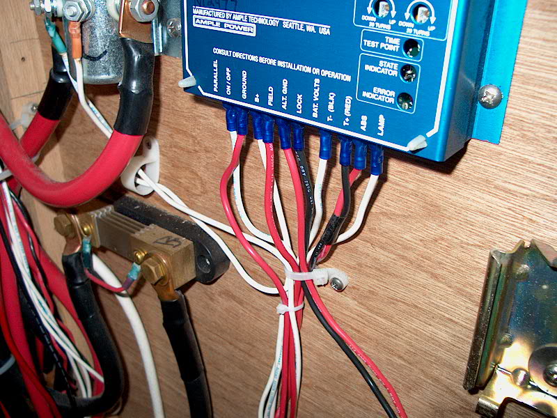
Because the system is set up with an external
regulator, it is easy to incorporate a switch into the circuit. The
regulator is powered through the ignition circuit; turning the key switch on
supplies power to the regulator, which then allows the alternator to charge the
batteries. If you disconnect the regulator while the engine is
running, the alternator stops charging. Sure, the alternator keeps
spinning, but is producing no power. Therefore, all I needed to do
was install a switch somewhere so that I could turn the regulator on and off at
will.
|
|
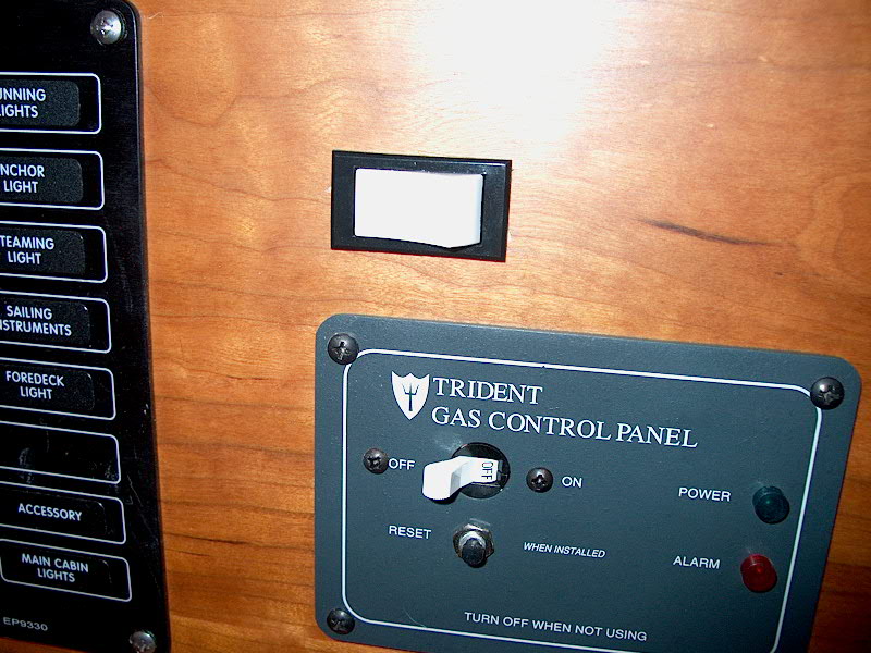 I picked up a rocker switch from the store and
installed it on my electrical board, above the LPG system controls.
Because it is difficult to cut holes out of this panel now that all the things
are wired--plus, it's such a small hole--I used a 1/4" drill bit to drill
all around the perimeter of the area I had marked out for the switch.
Then, I used a serrated utility knife to remove the rest of the material, and
fine tuned it with a file until the switch fit. The switch has a narrow
flange that does not allow much margin for error, and also relies upon a
friction fit, so I took it slowly to ensure that I didn't make the hole too
large. I was careful not to run into any of the existing wires behind the
panel while I worked. I picked up a rocker switch from the store and
installed it on my electrical board, above the LPG system controls.
Because it is difficult to cut holes out of this panel now that all the things
are wired--plus, it's such a small hole--I used a 1/4" drill bit to drill
all around the perimeter of the area I had marked out for the switch.
Then, I used a serrated utility knife to remove the rest of the material, and
fine tuned it with a file until the switch fit. The switch has a narrow
flange that does not allow much margin for error, and also relies upon a
friction fit, so I took it slowly to ensure that I didn't make the hole too
large. I was careful not to run into any of the existing wires behind the
panel while I worked.
|
|
 With the switch installed, I ran a doubled piece
of #14 AWG red wire from behind the panel, along one of my existing wire chases,
and into the engine room. Once there, I connected one of the wires to the
existing power supply (which runs from the ignition switch and, originally,
directly to the regulator on/off spade); this wire now formed a continuous run
up to behind the new switch. The other wire, which will connect to the
other side of the new switch, I ran up to the regulator on/off tab and connected
it with a spade connector. With the switch installed, I ran a doubled piece
of #14 AWG red wire from behind the panel, along one of my existing wire chases,
and into the engine room. Once there, I connected one of the wires to the
existing power supply (which runs from the ignition switch and, originally,
directly to the regulator on/off spade); this wire now formed a continuous run
up to behind the new switch. The other wire, which will connect to the
other side of the new switch, I ran up to the regulator on/off tab and connected
it with a spade connector.
|
|
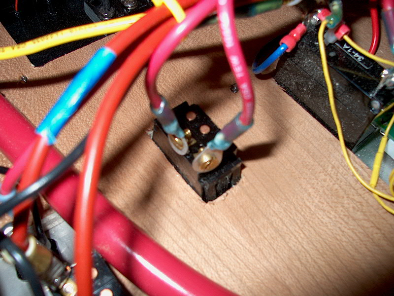
 Then I made up the connections behind the new
switch. Without paying attention to which wire was which, I connected them
to the two screws on the back of the switch with ring terminals.
Later, when I run the engine again, I'll determine which switch position is on
and which is off, and install an indicator as necessary. Then I made up the connections behind the new
switch. Without paying attention to which wire was which, I connected them
to the two screws on the back of the switch with ring terminals.
Later, when I run the engine again, I'll determine which switch position is on
and which is off, and install an indicator as necessary.
|
|