|
Sailing Hardware
This page was last
updated on 22 June 2002.
Garhauer Solid Boom Vang
I love Garhauer. I can't believe I never knew about the
stuff until about a year ago. The hardware is beautiful, and high
quality--all for an amazingly low price. All boatowners owe it to
themselves to at least check it out as an option. On top of that, the
customer service is excellent, and I even had a nice personal conversation with
the guy who built my vang when he called to ask a question about some
measurement or another. Fantastic. They require a tracing of your
mast and boom profiles; to do this, use a piece of ordinary plumbing solder and
wrap it around the mast and boom where the vang will attach. Then, trace
this profile onto a piece of paper and send it to Garhauer. In return, you
get custom-made stainless steel brackets that fit perfectly to your own spars.
My vang is model
#RV20-1 (for 28'-33' boats), for those interested. At the time (2001),
the cost was about $225. In 2003, I see that the price has gone up to a
still-rockbottom $253.
|
|
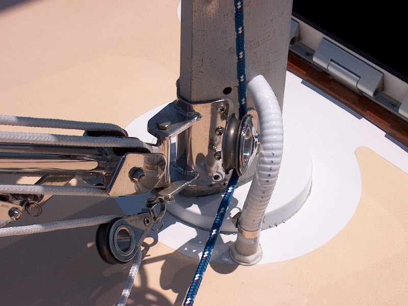
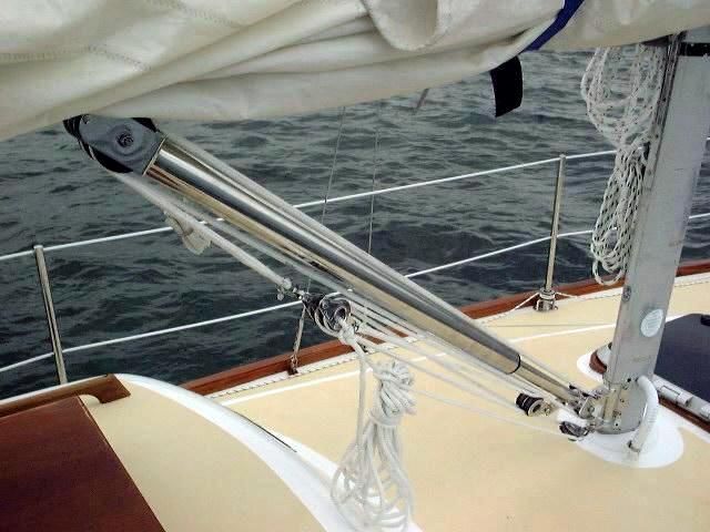
 Installing
the beautiful vang was really much simpler than I ever imagined. With the
vang fully assembled and attached to the mast and boom brackets--the way it
comes from the factory, I first installed the mast bracket at the base of the mast--just eight screws. Installing
the beautiful vang was really much simpler than I ever imagined. With the
vang fully assembled and attached to the mast and boom brackets--the way it
comes from the factory, I first installed the mast bracket at the base of the mast--just eight screws.
|
 Then, according to the instructions, I raised the end of the boom (using the
main halyard) up to about 40
degrees above horizontal, released the vang tension, and held the upper bracket
up against the sharply angled boom, thus marking for two center holes in the boom bracket. The directions say to install the bracket
through the two center holes first, then see how the lift is--if it's too high,
you move the bracket one way, if the boom lifts
Then, according to the instructions, I raised the end of the boom (using the
main halyard) up to about 40
degrees above horizontal, released the vang tension, and held the upper bracket
up against the sharply angled boom, thus marking for two center holes in the boom bracket. The directions say to install the bracket
through the two center holes first, then see how the lift is--if it's too high,
you move the bracket one way, if the boom lifts  too low (with the halyard or
topping lift released) you move it the other way. I secured the two middle
screws and released the halyard m boom was lifting too
high, so I moved the bracket aft one hole, as indicated by the instructions, and
checked it again--OK--and drilled the
remaining holes and secured it with screws. too low (with the halyard or
topping lift released) you move it the other way. I secured the two middle
screws and released the halyard m boom was lifting too
high, so I moved the bracket aft one hole, as indicated by the instructions, and
checked it again--OK--and drilled the
remaining holes and secured it with screws. |
|
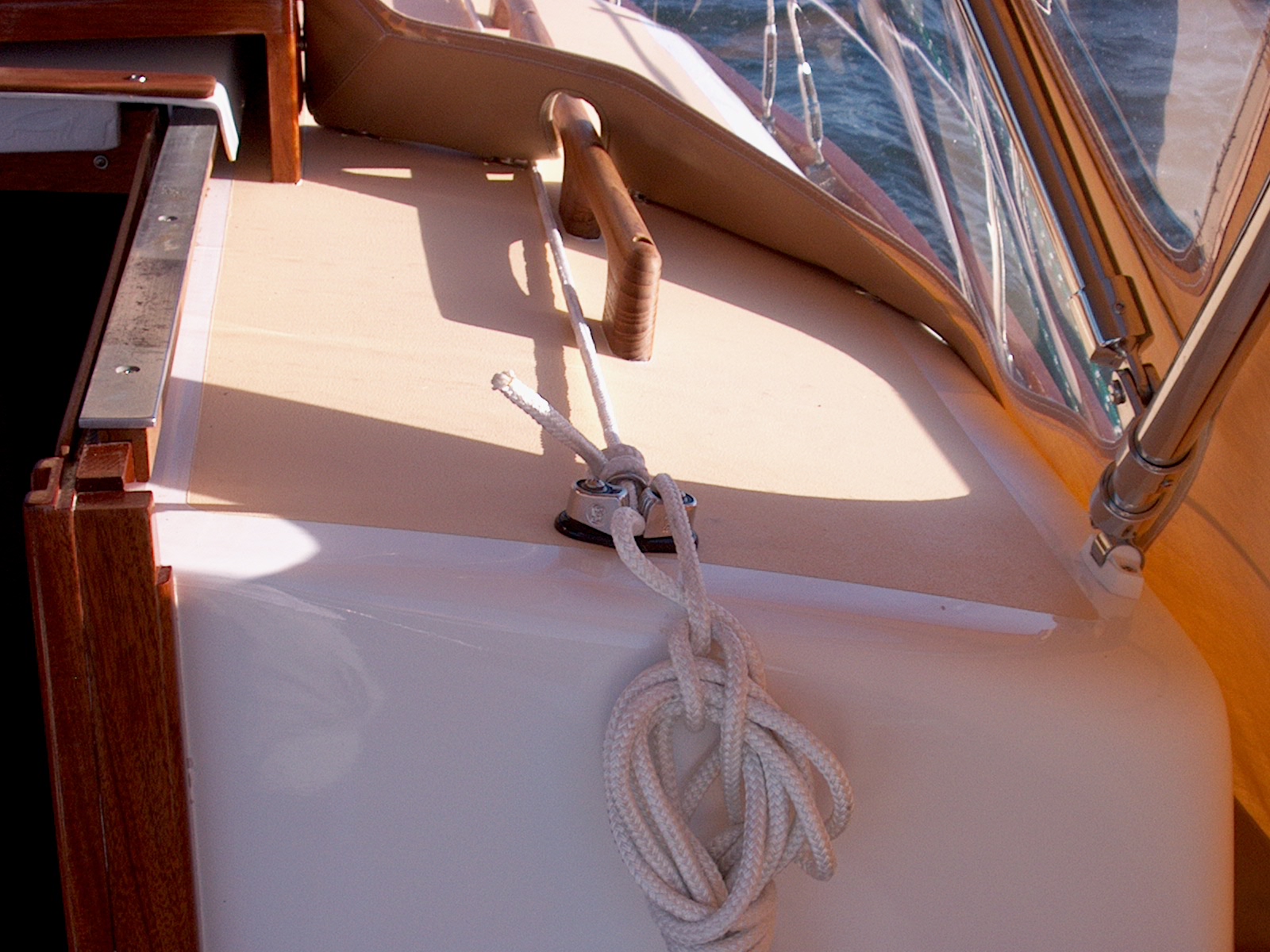
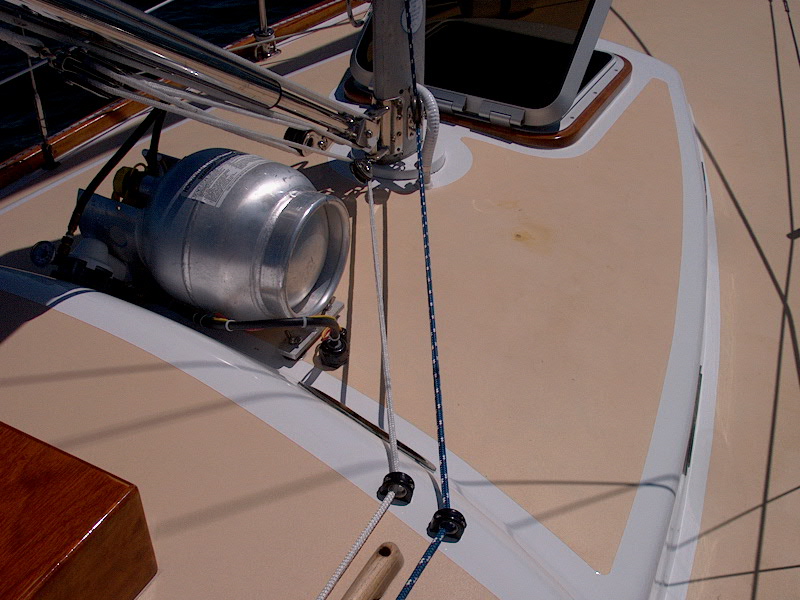
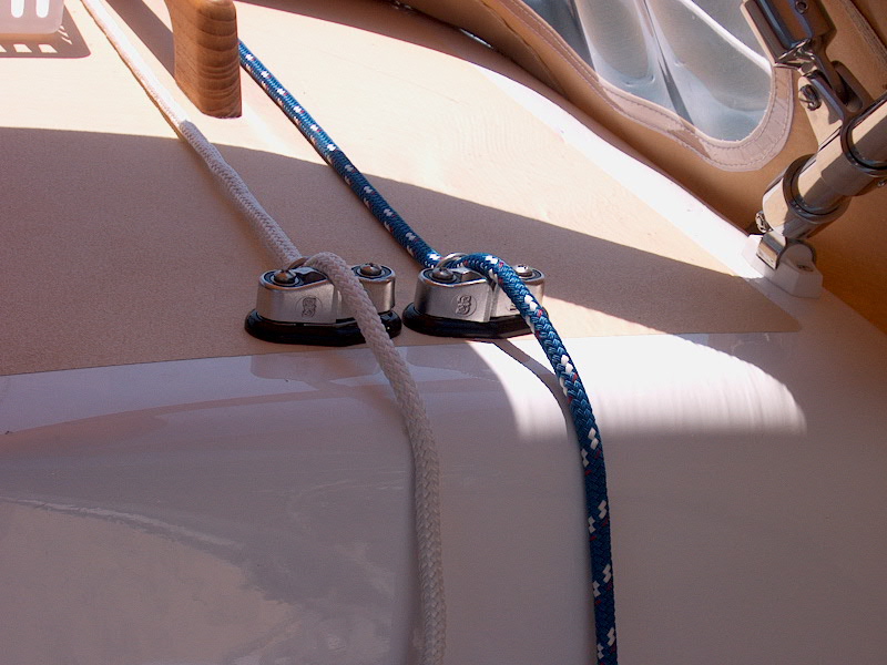
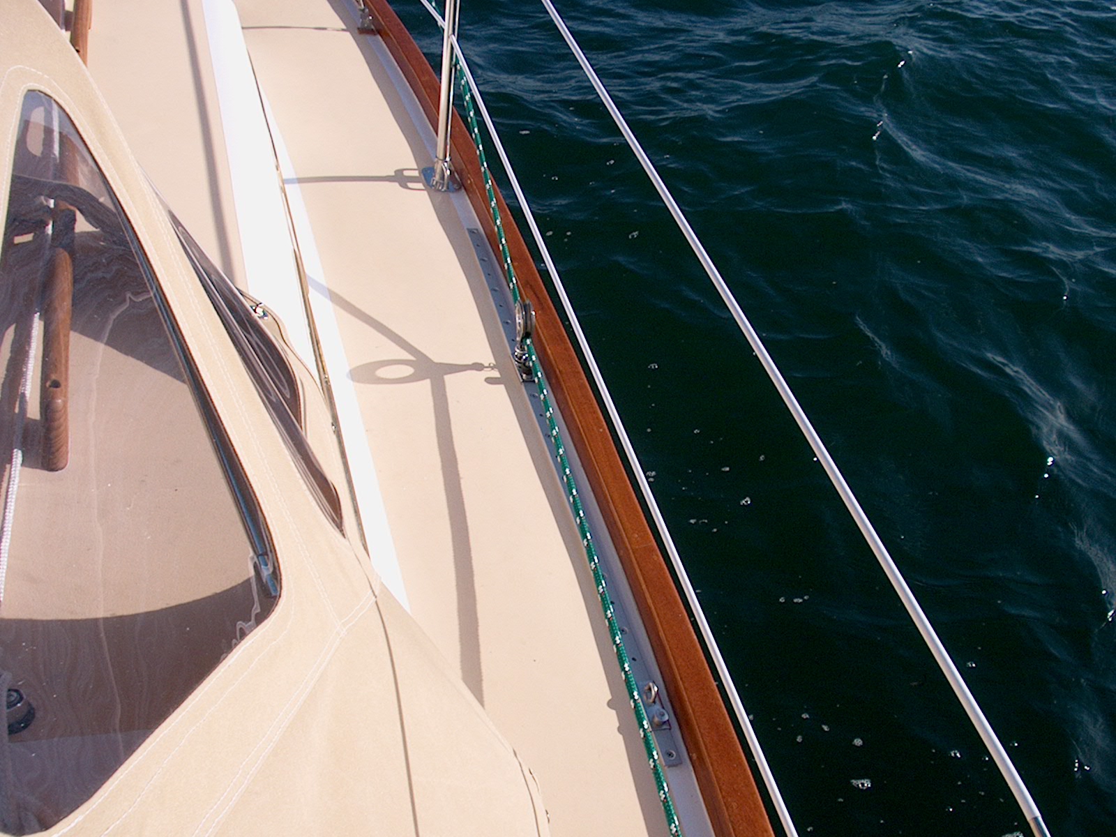
   I ran the control line aft
to
the cockpit through a bulls eye fairlead at the forward end of the coachroof,
beneath the dodger alongside the handrail, and to a Schaefer cam cleat I
installed near the cockpit. The vang did not come with a means for
securing the line and/or adjusting the tension from the mast base, but I imagine
that you could order or add a cam cleat at the bottom end and do your
adjusting from there. It is undeniably more convenient from the cockpit,
however.
I ran the control line aft
to
the cockpit through a bulls eye fairlead at the forward end of the coachroof,
beneath the dodger alongside the handrail, and to a Schaefer cam cleat I
installed near the cockpit. The vang did not come with a means for
securing the line and/or adjusting the tension from the mast base, but I imagine
that you could order or add a cam cleat at the bottom end and do your
adjusting from there. It is undeniably more convenient from the cockpit,
however.
|
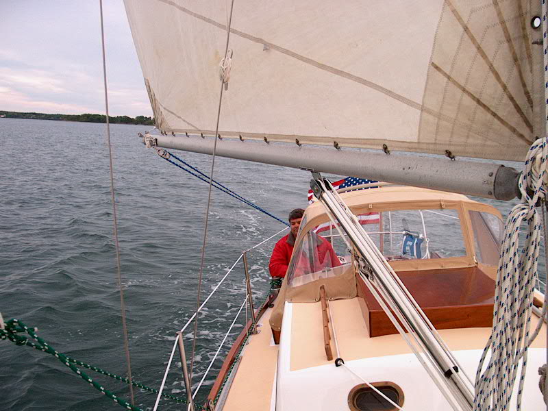
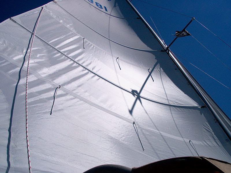
| The vang is beautiful, works very well (and easily), and, best
of all, eliminates the need for an annoying topping lift on the boom-which I
never even installed, anticipating the solid boom vang. It supports the
boom when you lower the sail--although I find it necessary to install the main
halyard at the end of the boom to give the sheet something to tightly pull
against and prevent the boom from swinging. Its ease of adjustment and
high power means that your mainsail will always have a superior shape, and it
doesn't lose its effectiveness when you ease the sheet way out; instead, this is
where it is most effective at creating a more efficient sail shape. |
|
Garhauer Mainsheet Tackle
 I
made up the mainsheet tackle with some 3/8" line and two Garhauer blocks--a
fiddle block with cam cleat, and a regular fiddle block. This gives a 4:1
ratio. The arrangement is pinned to the boom and traveler, and looks
great. These blocks are such a good value I can hardly stand it. I
made up the mainsheet tackle with some 3/8" line and two Garhauer blocks--a
fiddle block with cam cleat, and a regular fiddle block. This gives a 4:1
ratio. The arrangement is pinned to the boom and traveler, and looks
great. These blocks are such a good value I can hardly stand it.
The line is 90' of 3/8" Sta-Set (New England Ropes)--a
little longer than necessary, and a real pain, truth be told. During the
season I pushed the boom all the way out and checked to see how much line was
required; I was able to cut about 15' off the line, which made the clutter in
the cockpit a little more manageable.
|
|
Running Rigging
All running rigging is, of course, new. I replaced the
halyards--Sta-Set X for the genoa, Sta-Set for the mainsail and spinnaker-before the mast went up (duh!). The mainsheet is described above;
genoa sheets are 45' of 7/16" Sta-Set.
Genoa Lead Tracks and
Cars
My original plan was to install the genoa tracks on the wooden
toerail, mainly to avoid causing interference with my desired stanchion
placement. On the advice of my sail loft, I waited until the new genoa was
complete before installing the tracks, so I could be sure to put them in
the right place.
The lead for the new genoa ended up being farther forward than
I had anticipated--a good thing. To figure out the lead, I sighted an
angle from the clew of the sail up to about midway up the luff, and projected
that line down to the rail. It ended up about halfway between my second
and third stanchions. (The sail is a 130%.) This allowed me to
install my 4' tracks on the sidedeck between the two stanchions, which made life
a little easier, since installing them on the toerail, while a good choice,
would have required filling the void (from underneath) formed by the original
molded toerail, to give the washers and nuts something flat to bear
against. I had dreaded this from the beginning, and, with the boat in the
water and ready to sail except for the tracks, I welcomed an easier solution.
|
|
 There
are 13, 1/4" bolts that secure each track. To install them, I placed
the track where I wanted it and drilled the first hole, using the appropriate
drill bit for a 1/4-20 tap. Then, I tapped the hole, and partially
inserted a bolt to hold the track in place. Then, I repeated the procedure
on the aftermost bolt. With the two bolts to hold the track in the right
position, I drilled for the other 11 bolts, then removed the track, tapped each
hole (a lengthy process) and milled a small countersink at the top of each to
provide for a little pocket of sealant. Then, I cleaned the area, l aid
down a bed of polysulfide, and bolted the track in place. I repeated the
procedure on the other side. I used 1-1/2" fender washers on the
underside to spread the load. There
are 13, 1/4" bolts that secure each track. To install them, I placed
the track where I wanted it and drilled the first hole, using the appropriate
drill bit for a 1/4-20 tap. Then, I tapped the hole, and partially
inserted a bolt to hold the track in place. Then, I repeated the procedure
on the aftermost bolt. With the two bolts to hold the track in the right
position, I drilled for the other 11 bolts, then removed the track, tapped each
hole (a lengthy process) and milled a small countersink at the top of each to
provide for a little pocket of sealant. Then, I cleaned the area, l aid
down a bed of polysulfide, and bolted the track in place. I repeated the
procedure on the other side. I used 1-1/2" fender washers on the
underside to spread the load.
|
|
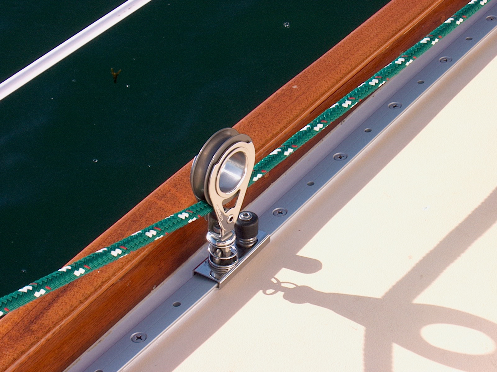
 With
the tracks installed, I could install my track cars, made, of course, by Garhauer. With
the tracks installed, I could install my track cars, made, of course, by Garhauer.
|
|
Reefing
Gear
Our new mainsail has two sets of reef points. At some
point during the boat restoration project, I had stripped all the lousy,
undersized hardware off the boom, so there was no way to reef the sail--not that
the old hardware, in its original location, would have worked for the new sail
anyway.
Rigging the reefing gear became a priority project for two
reasons: first, we were planning a cruise, and thought that reefing
capability might be nice...and, second, I had recently sailed the boat on a
windy day when a reef was really required, but not possible. I spent a
little time thinking about how I wanted to proceed, then went and spent way too
much money on the gear at the local store. Fortunately, I can return a
fair bit of what I bought--I bought stuff for a couple scenarios, not knowing
which way was going to work better. On a beautiful, warm, sunny,
windlass day in June I went to work setting up a basic system.
|
|
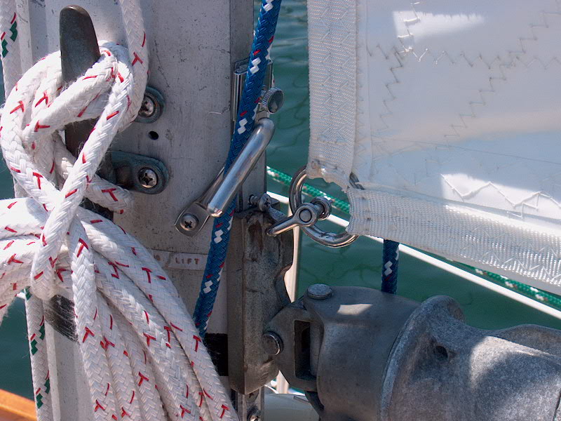 Each
reef requires two load points, one on each side of the boom, plus a way to hold
the luff cringle in place at the gooseneck. For this, I chose a simple
hook, onto which I thread the cringle. Then, I pull the halyard up tight
again. To install it, I drilled and tapped an appropriately sized hole in
the mast, after determining the correct location using the sail as a guide. Each
reef requires two load points, one on each side of the boom, plus a way to hold
the luff cringle in place at the gooseneck. For this, I chose a simple
hook, onto which I thread the cringle. Then, I pull the halyard up tight
again. To install it, I drilled and tapped an appropriately sized hole in
the mast, after determining the correct location using the sail as a guide.
Next, I turned my attention to the leech. Here, lines
are used to pull the sail tightly down to the boom in the appropriate
spot. First, I lowered the sail and attached the luff cringle for each
reef in turn. Then, I pulled, by hand, the sail tightly down and out on
the boom at the leech, and made a mark on the boom for each reef point.
Ideally, the lines should lead slightly aft from these cringles, so that you
pull the new "outhaul" tight as well as tightening the leech properly.
|
|
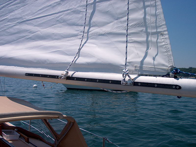 I
decided to install a T track on the port side of the boom, which would allow
adjustment fore and aft if necessary. I had a 4-foot section on hand, so I
drilled and tapped for the 12 1/4-20 machine screws that hold it on. There
is plenty of adjustment room if necessary, and probably room for a third reef
point someday. I installed two cars on the track, onto which I will tie
the reefing lines on that side of the boom. I
decided to install a T track on the port side of the boom, which would allow
adjustment fore and aft if necessary. I had a 4-foot section on hand, so I
drilled and tapped for the 12 1/4-20 machine screws that hold it on. There
is plenty of adjustment room if necessary, and probably room for a third reef
point someday. I installed two cars on the track, onto which I will tie
the reefing lines on that side of the boom.
|
|
 On
the starboard side of the boom, I installed two cheek blocks, through which the
lines pass. Again, these are located slightly aft of the cringle location,
so the lines, when pulled taut, stretch out the foot of the sail. These are
installed with four #10-24 pan head machine screws, for which I drilled and
tapped the boom. Then, forward of each block, I installed a large jam
cleat for securing each line. On
the starboard side of the boom, I installed two cheek blocks, through which the
lines pass. Again, these are located slightly aft of the cringle location,
so the lines, when pulled taut, stretch out the foot of the sail. These are
installed with four #10-24 pan head machine screws, for which I drilled and
tapped the boom. Then, forward of each block, I installed a large jam
cleat for securing each line.

|
|
UPDATE
(3/12/02) This setup was OK for the immediate need, and it
worked for the several times we reefed during the season. However, with
the reefing line adjustments at the aft end of the boom, I rapidly discovered
that it was inconvenient at best, unsafe at worst, to have to pull the leech of
the sail down from that position. It was OK at the mooring, but very
difficult underway. As the season drew to a close, I knew that I would
have to change the setup for next season in order to make it much easier and
more efficient to reef. During the first part of the winter, I thought up
the system that I wanted to implement.
Because my main halyard is
located on the mast--and is going to stay there, since I have no desire to run
it aft--I wanted a reefing system that could be completed entirely from one
position: at the mast. This meant that I would have to run the
reefing lines forward along the boom, and come up with a good way to operate
them from there.
I decided that a new sheet
stopper, combined with a winch on the boom, would be the best way to handle the
reefing lines. The sheet stopper is not only a convenient way to secure
the lines, but is also necessary to allow a single winch to handle the two
reefing lines at once. Of course, I turned to Garhauer for this, and
purchased a dual sheet stopper (# 11-12S). Another nice piece of equipment
from Garhauer (with one small caveat...read on for details).
The winch raised a little more
concern. I sure didn't want to buy a new winch, as they are
budget-busters. Unfortunately, Garhauer hasn't branched out into winch
manufacturing yet. I had two of the old South Coast winches from my
cockpit, which were in decent condition. However, they were a little large
(height wise) and I prefer more modern "newfangled" winches
anyway. It was at this point that a chance visit with a friend brought to
light complementary equipment deficiencies: he wanted more of the old
winches, but his boat had come with newer winches on his mast. I wanted
the newer winches, but had the old ones. And, suddenly, in the old
fashioned and highly efficient spirit of bartering, we traded--old for new, new
for old. Including handles. Thanks, Jeff!
In return for my two bronze South
Coast sheet winches and handles, I received two small (I forget the number)
Barlows with a few spare handles. One of these would be perfect for use
with the reefing system--it's fairly low profile and not too heavy, but will be
easily powerful enough to do the minimal work required. The winch was in
great shape, and I didn't even see the need to service it once I had taken it
apart for installation.
|
|
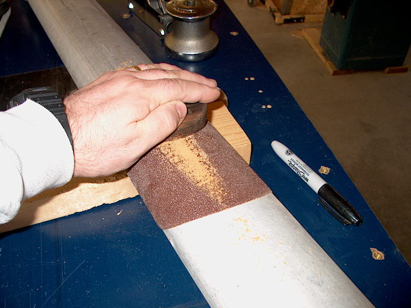
 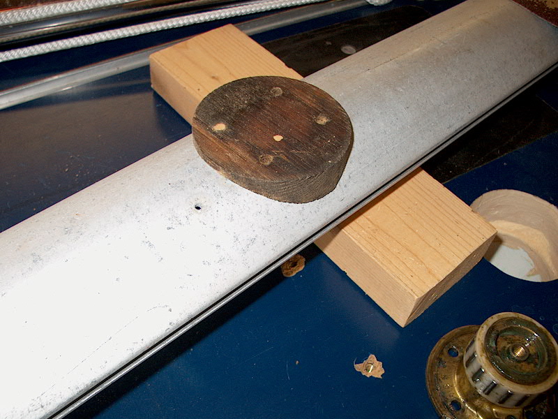 Along
with the winch, I received teak base pads that had been shaped to conform to the
shape of the mast on which they had been installed. The shape wasn't quite
right for my boom, so I had to make some minor modification and shape them to
fit the spar. To do this, I stuck an 8" 40-grit sanding disc (PSA)
onto the boom in the area that the winch was to be installed, and thusly sanded
the teak block to the proper shape. It worked great, and didn't take too
much time. I even saved the wood flour created for use as a coloring agent
in some future batch of epoxy. When the sanding was complete, I had a pad
that fit nearly perfectly. I stopped just short of the perfect fit because
I didn't want the pad to get too thin in the middle. Besides, the center
portion was in full contact, and that's where the four boltholes are. I
mainly didn't want any gaps beneath that area. Along
with the winch, I received teak base pads that had been shaped to conform to the
shape of the mast on which they had been installed. The shape wasn't quite
right for my boom, so I had to make some minor modification and shape them to
fit the spar. To do this, I stuck an 8" 40-grit sanding disc (PSA)
onto the boom in the area that the winch was to be installed, and thusly sanded
the teak block to the proper shape. It worked great, and didn't take too
much time. I even saved the wood flour created for use as a coloring agent
in some future batch of epoxy. When the sanding was complete, I had a pad
that fit nearly perfectly. I stopped just short of the perfect fit because
I didn't want the pad to get too thin in the middle. Besides, the center
portion was in full contact, and that's where the four boltholes are. I
mainly didn't want any gaps beneath that area.
|
|
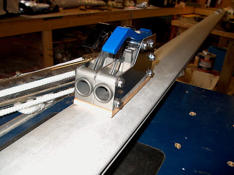
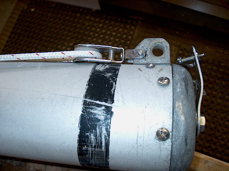
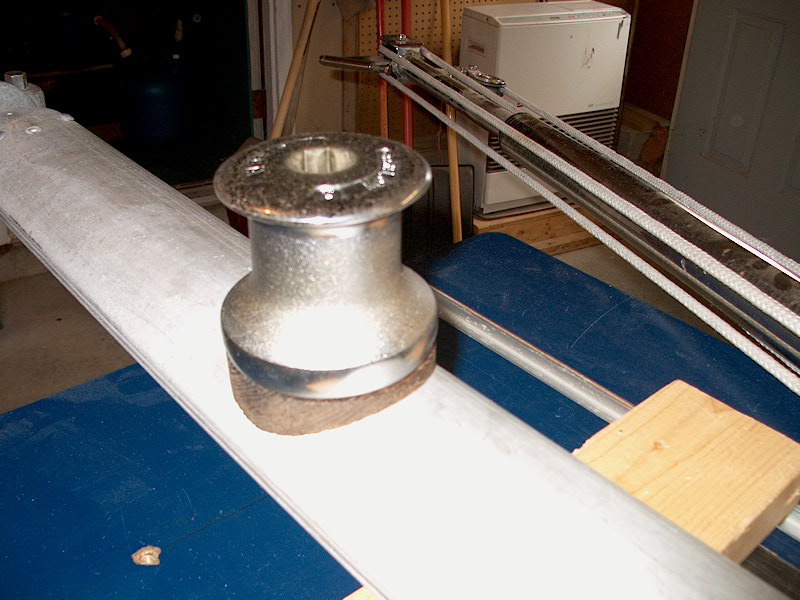 I
installed the winch near the forward end of the boom with four 1/4-20 pan head
machine screws, 1" in length. I drilled and tapped the boom to accept
the bolts. Obviously, there's no way to actually bolt the hardware to the
boom, as the interior is inaccessible. I reassembled the winch (the top
comes right off by releasing an Allen screw that's located inside the star drive
recess) and this part of the project was complete. I
installed the winch near the forward end of the boom with four 1/4-20 pan head
machine screws, 1" in length. I drilled and tapped the boom to accept
the bolts. Obviously, there's no way to actually bolt the hardware to the
boom, as the interior is inaccessible. I reassembled the winch (the top
comes right off by releasing an Allen screw that's located inside the star drive
recess) and this part of the project was complete.
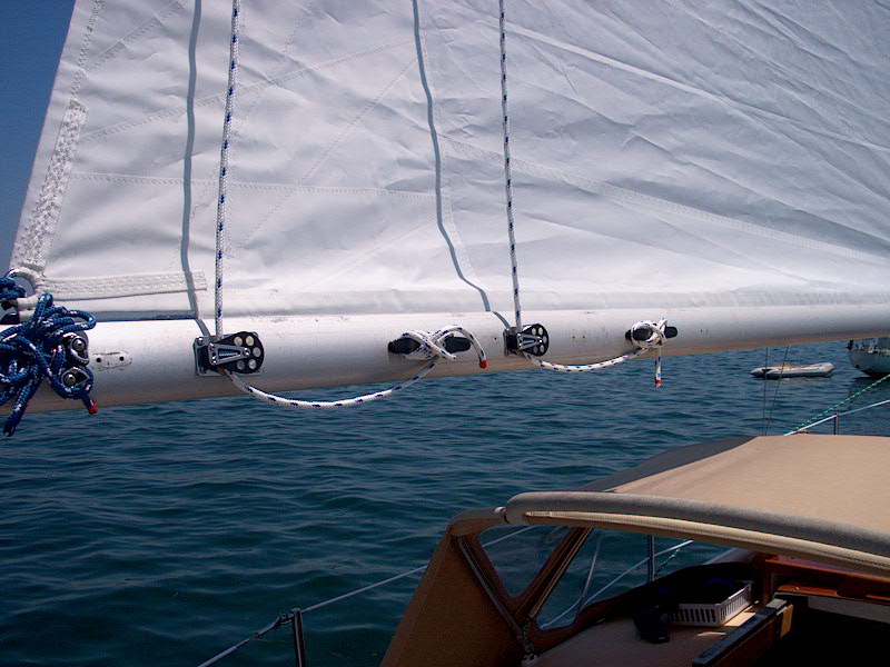
Next, I prepared to install the
dual sheet stopper (rope clutch). I determined the best position for it to
be a little over a foot aft of the winch--maybe closer to 18". This
keeps the controls close enough to the forward end of the boom, but also keeps
the stopper forward of the area where the boom vang is attached. I figured
it would be best to stagger these attachment points; in any case, I didn't
adjust anything one way or the other for this reason--it just happened to end up
in this convenient arrangement.
|
|
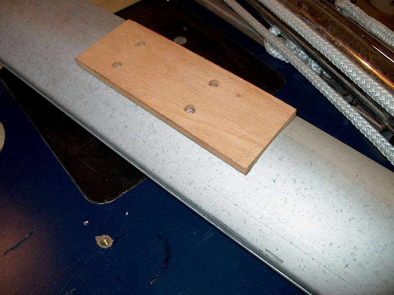
 Out
of a scrap piece of 5/16" thick mahogany, I cut to fit a pad for the
stopper and, using the same technique described above, sanded the bottom along
the boom so that it would conform to the shape. The stopper base, at
2-1/2", is narrow enough that a thin board is more than sufficient to make
up for any gaps because of the curvature of the boom, and I probably could have
gotten away without it at all. However, given the ease with which I had been
able to reshape the winch pad, I decided to go ahead with a similar pad for the
stopper. Once I had cut and sanded the pad to shape, I carefully marked
the outline of the bolt holes and drilled them slightly oversize. Then,
after checking carefully the fit, I drilled and tapped the boom to accept 1/4-20
fasteners. Out
of a scrap piece of 5/16" thick mahogany, I cut to fit a pad for the
stopper and, using the same technique described above, sanded the bottom along
the boom so that it would conform to the shape. The stopper base, at
2-1/2", is narrow enough that a thin board is more than sufficient to make
up for any gaps because of the curvature of the boom, and I probably could have
gotten away without it at all. However, given the ease with which I had been
able to reshape the winch pad, I decided to go ahead with a similar pad for the
stopper. Once I had cut and sanded the pad to shape, I carefully marked
the outline of the bolt holes and drilled them slightly oversize. Then,
after checking carefully the fit, I drilled and tapped the boom to accept 1/4-20
fasteners.
|
|
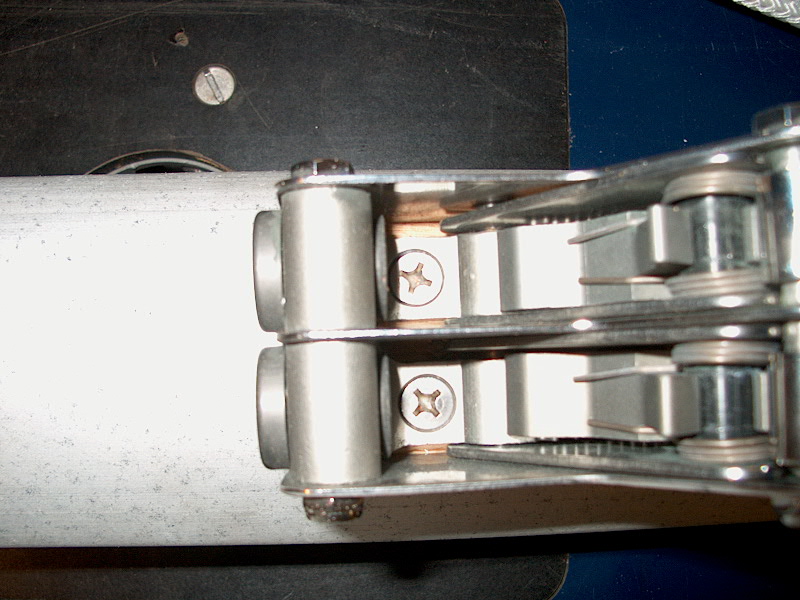
 Attaching
the stopper with four 1-1/4" flathead machine screws was a little tough,
and brought to light the only complaint with the Garhauer stopper. The
bottom of the stopper is undoubtedly machined for 1/4-20 fasteners, and the
forward two were easy to install right through the top. Attaching
the stopper with four 1-1/4" flathead machine screws was a little tough,
and brought to light the only complaint with the Garhauer stopper. The
bottom of the stopper is undoubtedly machined for 1/4-20 fasteners, and the
forward two were easy to install right through the top.
|
|
 Installing
the back two bolts requires getting them down to the bottom of the stopper by
adjusting the two handles just right to open up a space above the machined bolt
holes. To help get the screws in there, I applied a dab of some sticky
wood filler I had around to the end of the screwdriver, then pressed the screw
on. The wood filler worked very well to hold the screw in place at the tip
of the screwdriver, allowing me to get the screws started. However, I
found that it was just about impossible to get the bugle heads of the bolts
through the available opening created by moving the stopper controls! The
openings just weren't large enough for the heads. Only by moving Installing
the back two bolts requires getting them down to the bottom of the stopper by
adjusting the two handles just right to open up a space above the machined bolt
holes. To help get the screws in there, I applied a dab of some sticky
wood filler I had around to the end of the screwdriver, then pressed the screw
on. The wood filler worked very well to hold the screw in place at the tip
of the screwdriver, allowing me to get the screws started. However, I
found that it was just about impossible to get the bugle heads of the bolts
through the available opening created by moving the stopper controls! The
openings just weren't large enough for the heads. Only by moving  the
controls back and forth and angling the screw one way and the other did I
finally get them through, and then it was a tight fit for my #3 Phillips
screwdriver. I would think that our friends at Garhauer could have made
this available opening just a tiny bit larger without ruining the design
of the stopper. 1/8" or less additional room would have been all that
was required. Anyway, I did get them in, and tightened all four
securely. All's well that ends well. the
controls back and forth and angling the screw one way and the other did I
finally get them through, and then it was a tight fit for my #3 Phillips
screwdriver. I would think that our friends at Garhauer could have made
this available opening just a tiny bit larger without ruining the design
of the stopper. 1/8" or less additional room would have been all that
was required. Anyway, I did get them in, and tightened all four
securely. All's well that ends well.
|
|
|
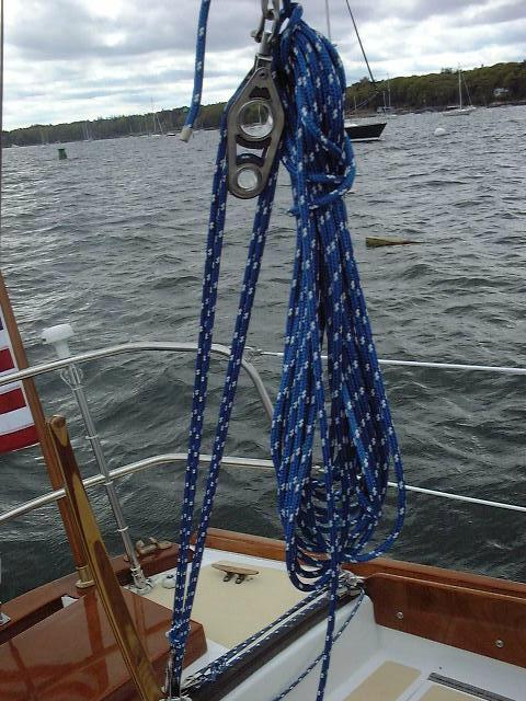
| When
the boat was launched, I rigged up the reefing lines. Storing these when
the sail is lowered is always a pain because there is so much excess line to
deal with, but I guess it's a necessary evil. However, the first test of
the new reefing system, during our first sail of the season, was a complete and unbridled
success--the new winch and line stopper made short work of the aft reefing
lines, and reefing is now extremely easy. |
|
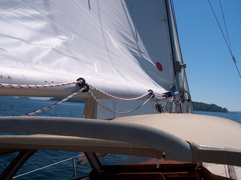
 Sailing
around during several weeks in a variety of conditions pointed out a couple
minor issues that I needed to take care of. The first thing was the slack
in the two reefing lines where they ran forward along the boom from the turning
blocks aft to the stopper further forward. The lines drooped here (since
they need to be left fairly slack or else they interfere with the leech).
To combat this problem, I installed two simple fairleads for each line--the
little Forespar bull's-eye fairleads. These have no function other than to
hold the line closer to the boom, so I just drilled and installed self-tapping
screws to hold them in place. Sailing
around during several weeks in a variety of conditions pointed out a couple
minor issues that I needed to take care of. The first thing was the slack
in the two reefing lines where they ran forward along the boom from the turning
blocks aft to the stopper further forward. The lines drooped here (since
they need to be left fairly slack or else they interfere with the leech).
To combat this problem, I installed two simple fairleads for each line--the
little Forespar bull's-eye fairleads. These have no function other than to
hold the line closer to the boom, so I just drilled and installed self-tapping
screws to hold them in place.
|
|
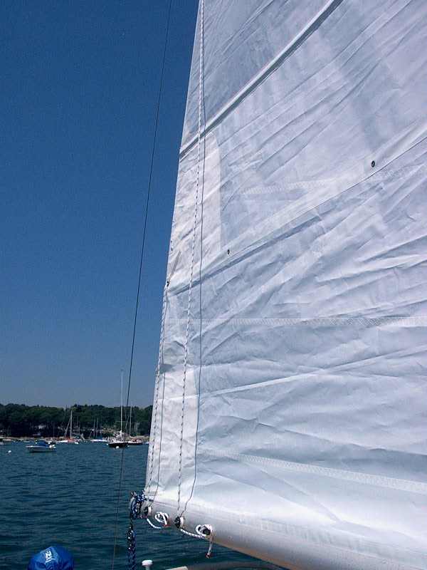
 The
other small thing I needed to deal with was to install some tie downs in the
grommets supplied for this purpose at each reef point--three per reef.
These little tiedowns not only help secure the excess folds of sail that are
present when reefed, but also help hold the center part of the sail (reefed)
tighter to the boom, improving sail shape. To make these, I cut lengths of
1/4" Sta-Set braided line to appropriate lengths (about 24-30").
After marking the center point of each of the six pieces, I partially raised the
sail (to make working on it easier) and threaded one of these lines through each
grommet as needed, leaving an equal amount hanging out each side. To hold
them in place in the center, a simple overhand knot on each side of the grommet
does the trick. The
other small thing I needed to deal with was to install some tie downs in the
grommets supplied for this purpose at each reef point--three per reef.
These little tiedowns not only help secure the excess folds of sail that are
present when reefed, but also help hold the center part of the sail (reefed)
tighter to the boom, improving sail shape. To make these, I cut lengths of
1/4" Sta-Set braided line to appropriate lengths (about 24-30").
After marking the center point of each of the six pieces, I partially raised the
sail (to make working on it easier) and threaded one of these lines through each
grommet as needed, leaving an equal amount hanging out each side. To hold
them in place in the center, a simple overhand knot on each side of the grommet
does the trick.
Cunningham
I fixed the gooseneck in place
because of the solid vang installation--the boom can't slide up and down
anymore--and, because of this, I needed to install a cunningham to help properly
tension the luff of the main and move the draft of the sail around as desired
for various conditions.
|
|
 Rigging
the cunningham was fairly straightforward. The sailmaker sewed an external
ring onto the sail, which they prefer to do after the fact instead of installing
a real ring through the sail. Rigging
the cunningham was fairly straightforward. The sailmaker sewed an external
ring onto the sail, which they prefer to do after the fact instead of installing
a real ring through the sail.
|
 For
the cunningham, I rigged a simple arrangement--I tied a line to the base of the
spinnaker halyard cleat on the port side of the mast, which happened to be in
the right location; I couldn't see a reason to install more hardware than
necessary. Then, the line runs through the cringle, and down to deck
level, where I installed a padeye on the mast to accept a snatch
block. For
the cunningham, I rigged a simple arrangement--I tied a line to the base of the
spinnaker halyard cleat on the port side of the mast, which happened to be in
the right location; I couldn't see a reason to install more hardware than
necessary. Then, the line runs through the cringle, and down to deck
level, where I installed a padeye on the mast to accept a snatch
block. |
|
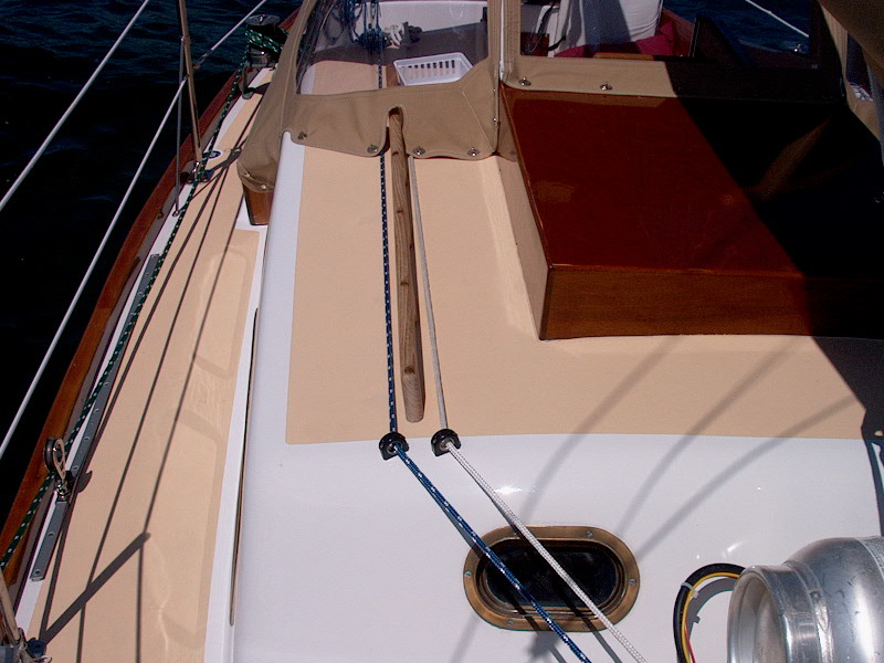
  Then,
the line runs up to another bull's eye next to the vang line on the cabin trunk,
and aft to the cockpit, where I installed another cam cleat. This makes it
easy and convenient to adjust. Then,
the line runs up to another bull's eye next to the vang line on the cabin trunk,
and aft to the cockpit, where I installed another cam cleat. This makes it
easy and convenient to adjust.
|
|
Outhaul
Controlling the fullness of the
foot of the sail is the job of the outhaul. The amount of adjustment you
do is in direct proportion to the convenience and efficiency of the outhaul
setup. Last year, I rigged up a ridiculous system using one line and a cam
cleat on the end of the boom. It held the sail in place, but forget about
adjustment, especially underway.
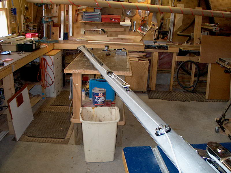
Once again, I decided that
leading the control to the forward end of the boom would be best. This
way, no matter how far out the boom is, the outhaul can still be
adjusted--important, since one might be most likely to ease the outhaul when the
boom is let out on a reach or run.
|
|
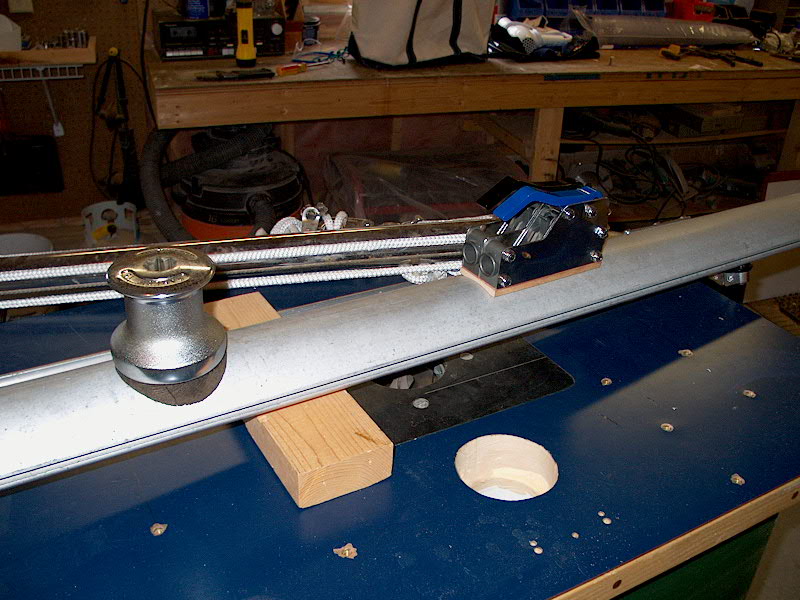
 The
arrangement is pretty simple. There is a small, single block attached to
the fitting at the end of the boom--an old block, to be sure, but I haven't yet
found a new one that fits as well. When I do, I'll install it. A
length of line runs through this block to the ring at the clew of the
mainsail. The other end leads forward along the boom to a point
approximately midway. Note that the lines in the photos are for
illustrative and setup purposes only, and will be replaced with "real"
line for actual use. (What is shown is only clothesline...) The
arrangement is pretty simple. There is a small, single block attached to
the fitting at the end of the boom--an old block, to be sure, but I haven't yet
found a new one that fits as well. When I do, I'll install it. A
length of line runs through this block to the ring at the clew of the
mainsail. The other end leads forward along the boom to a point
approximately midway. Note that the lines in the photos are for
illustrative and setup purposes only, and will be replaced with "real"
line for actual use. (What is shown is only clothesline...)
|
|
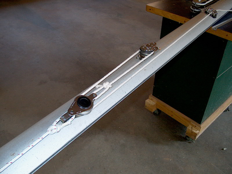 At
this point, the line attaches to a Garhauer fiddle block--a dead end, so
to speak. This block is not attached to the boom at all, and will move
back and forth according to the outhaul adjustment. This will soon become
more clear. About 18" further forward on the boom, I attached a
Garhauer cheek block (drilled and tapped, and secured with four 10-32
fasteners). To the other side of the fiddle block I attached a length of
line, which I then ran through the cheek block, back to the fiddle block and
then forward along the boom once more to a cam cleat that I installed several
feet from the gooseneck. At
this point, the line attaches to a Garhauer fiddle block--a dead end, so
to speak. This block is not attached to the boom at all, and will move
back and forth according to the outhaul adjustment. This will soon become
more clear. About 18" further forward on the boom, I attached a
Garhauer cheek block (drilled and tapped, and secured with four 10-32
fasteners). To the other side of the fiddle block I attached a length of
line, which I then ran through the cheek block, back to the fiddle block and
then forward along the boom once more to a cam cleat that I installed several
feet from the gooseneck.
This arrangement not only allows
for adjustment from the mast, but also provides a mechanical advantage that will
make adjustment much easier. Reviewing my American Merchant Seaman's
Manual, I note that the purchase at the end of the boom is 1:1, and the
moving tackle partway up the boom is 3:1. The total advantage is the
product of the two, so it is 3:1. If I added a moving block to the clew of
the sail, the advantage of the boom-end tackle would become 2:1, and the total
system advantage 6:1. When I rig the boat I'll see if there's enough room
there for a second block.
6/16/03 UPDATE! Over
the winter, I had my mainsail converted to a loose foot. This makes
adjusting the outhaul easy and desirable. Therefore, early during the 2003
season I noticed a need to have more convenient control over the outhaul; having
to go forward to adjust it on the boom was just difficult enough (especially
when singlehanding) that I tended not to do it. I also noticed that some
extra mechanical advantage might be nice, if I could get it. So I decided
to lead the control line aft to the cockpit, and to add a block at the end of
the boom to increase the advantage.
Please
click here to read more about this project.
|
|
|
|
|