|
Chain Locker
Bulkhead
This page was last updated on 3 March 2002
|
|
 As
the initial restoration project drew to a close in the spring of 2001, certain
projects had to be postponed in the interest of getting the boat in the water
and sailing. Many of these postponed projects were things that would have
been nice from the onset, but weren't really necessary for any reason except
convenience or cosmetics. Among these projects: bookshelves, a few
minor trim pieces and--finishing off the chain locker bulkhead in the vee berth. As
the initial restoration project drew to a close in the spring of 2001, certain
projects had to be postponed in the interest of getting the boat in the water
and sailing. Many of these postponed projects were things that would have
been nice from the onset, but weren't really necessary for any reason except
convenience or cosmetics. Among these projects: bookshelves, a few
minor trim pieces and--finishing off the chain locker bulkhead in the vee berth.
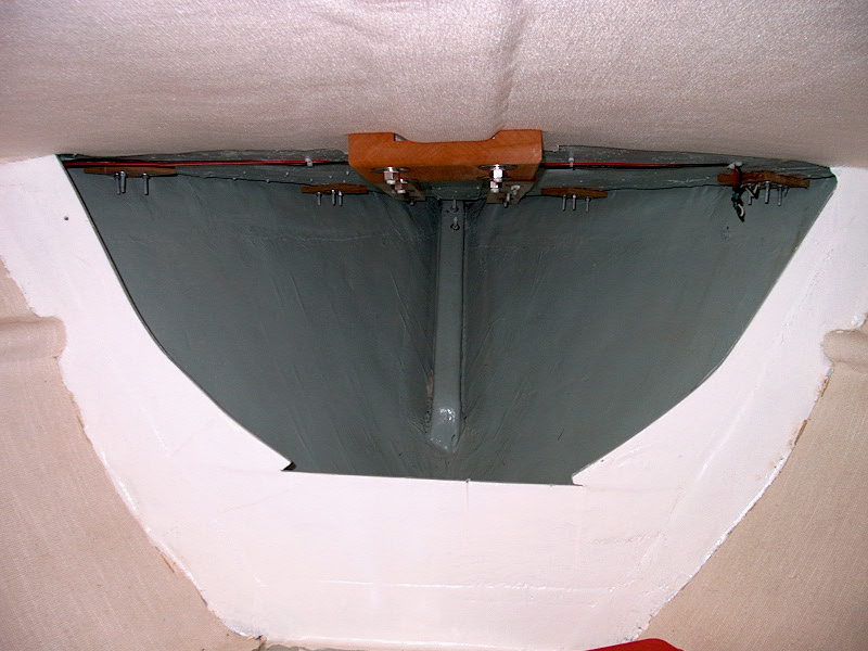
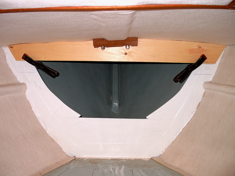
From the factory, the Triton came with a
partial bulkhead separating the chain locker from the vee berth. There is
a large opening, which is great for access or ventilation, but is not
particularly attractive. I painted it bright white and we lived with it
for the first season. But I knew that once I got the boat home in the back
yard again, I would not let another season begin without building a more
attractive bulkhead here.
The new bulkhead will serve two
purposes: to be more attractive, but also to assist in stiffening the
foredeck above. Part of the structure behind the new surface will be a
laminated plywood beam spanning the width of the deck up there where you can see
that there is no structure whatsoever as the boat came from the factory. The new
beam will be behind a semi-structural--but mostly cosmetic--mahogany bulkhead
that will cover the entire area.
|
|
 The
first order of business was to make a template of the shape of the overhead
(underside of the deck), and then of the entire bulkhead area. To ensure
that the new deck beam, and the mahogany bulkhead, are perfect fits, I intend to
make a full-size template of 1/4" plywood first, which I will in turn use
to cut out the actual finished pieces. This is a multi-step process,
beginning with an accurate scribed template that will be used to form the deck
beam and the top side of the new bulkhead. The
first order of business was to make a template of the shape of the overhead
(underside of the deck), and then of the entire bulkhead area. To ensure
that the new deck beam, and the mahogany bulkhead, are perfect fits, I intend to
make a full-size template of 1/4" plywood first, which I will in turn use
to cut out the actual finished pieces. This is a multi-step process,
beginning with an accurate scribed template that will be used to form the deck
beam and the top side of the new bulkhead.
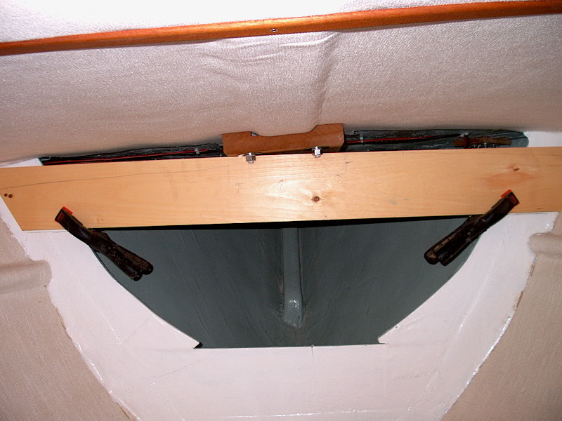
To begin, I grabbed a 6"
piece of scrap pine from my shop and cut it to approximately the maximum width
of the top of the bulkhead--somewhere around 52 or 54". The wide
piece was necessary because the beam and bulkhead have to fit around a mahogany
backing block in the center (which is the backing for the big mooring bit), and
scribing it to fit will require quite a bit to be taken off the top. With
the ends cut at an angle to more than accommodate the shape of the hull, I
clamped it in place as high as it could go on the bulkhead. Unsurprisingly,
I found that the deck above was not symmetrical in the least, and the board
looked crooked when it was in fact straight and level as measured from the vee
berth platform and also the bottom of the cutout, which is parallel to the vee
berth. You can see the additional space above the board on the right side,
and also in the center where the mahogany backing block is.
|
|
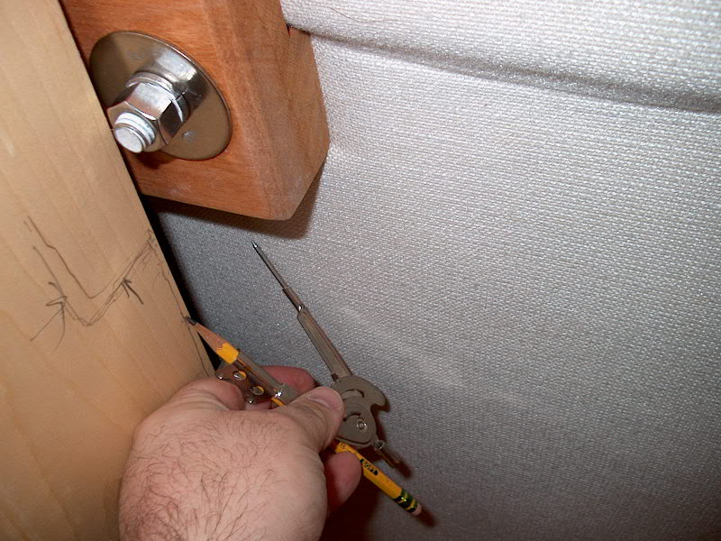 Once
I was satisfied that the template was level and straight, I scribed the shape of
the deck above onto the board using a schoolhouse compass. This is a
simple matter of setting the compass to somewhat more than the widest space
above the board and then, without changing the setting, letting the point side
of the compass run along the surface to be traced, while the pencil makes a
corresponding mark on the board. I traced the entire width, and also
marked where the board hit the existing bulkhead to help reference everything
later. Once
I was satisfied that the template was level and straight, I scribed the shape of
the deck above onto the board using a schoolhouse compass. This is a
simple matter of setting the compass to somewhat more than the widest space
above the board and then, without changing the setting, letting the point side
of the compass run along the surface to be traced, while the pencil makes a
corresponding mark on the board. I traced the entire width, and also
marked where the board hit the existing bulkhead to help reference everything
later.
|
|
 Cutting along this pencil line gets a close
approximation of the traced shape, but typically some fine tuning is
necessary. After my first cut, I fit the template in place and found that
there were still a few gaps on one side, so I remarked it with the scribe and
cut off the small resulting amount. When I put the template back in place, it
fit close to perfectly. Note again how uneven and out of kilter the
underside of the deck is--you can see that, although the bottom of the wooden
template is parallel with the bottom of the cutout and the surface of the vee
berth, there is much less material on the port side (left) than on the starboard
side of the template. You can also see how the mahogany backing
block in the center appears crooked as well. I also found that the
bulkhead is not square to the centerline of the boat--just like the other
bulkheads I have had to deal with on board. Cutting along this pencil line gets a close
approximation of the traced shape, but typically some fine tuning is
necessary. After my first cut, I fit the template in place and found that
there were still a few gaps on one side, so I remarked it with the scribe and
cut off the small resulting amount. When I put the template back in place, it
fit close to perfectly. Note again how uneven and out of kilter the
underside of the deck is--you can see that, although the bottom of the wooden
template is parallel with the bottom of the cutout and the surface of the vee
berth, there is much less material on the port side (left) than on the starboard
side of the template. You can also see how the mahogany backing
block in the center appears crooked as well. I also found that the
bulkhead is not square to the centerline of the boat--just like the other
bulkheads I have had to deal with on board.
|
|
With this critical template made, I moved on
to making a template for the entire bulkhead. Temporarily removing the
pine template, I taped up some pieces of pattern paper (blank newsprint) around
the three edges (sides and bottom), leaving the pieces approximately 1-2"
away from the curved part of the hull. Then, I reclamped the board in
place across the top and made some marks to reference it to the paper portion of
the template later. Setting my dividers to 3", and using a small vise
grips to keep them locked in place (they tend to slip), I carefully traced the
curvature of the hull (and the various undulations of the fiberglass) onto the
paper pattern--and onto the wood at the top edges. I forgot to take a
picture of the 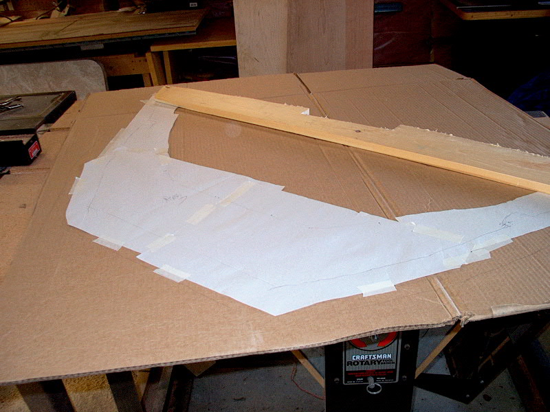 paper
template in place. While I had the paper on there, I also marked the rough
outline of the existing cutout onto the paper, so that I can easily determine
where to locate my door opening later. paper
template in place. While I had the paper on there, I also marked the rough
outline of the existing cutout onto the paper, so that I can easily determine
where to locate my door opening later.
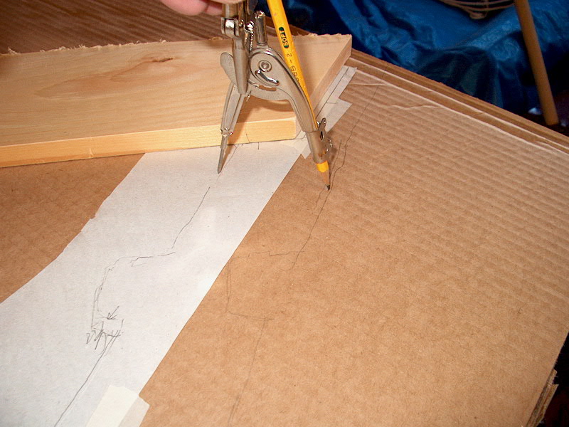
When the tracing was complete, I removed the
wooden board and the paper template (carefully) and took them to my shop.
I had intended to create a pattern on some thin plywood, but I discovered that I
didn't have as big a sheet as I had thought. I did have some heavy
corrugated cardboard that was big enough, however. Laying the cardboard on
a flat surface. I placed the paper template on top, and carefully spread it
out. I also laid the board across the top, as this is my template for the
top portion of the bulkhead. When I was satisfied that the paper was flat
and properly aligned, I used my dividers--still set at 3"--to transfer the
line onto the cardboard. I traced the line all the way around, and then
drew a line for the top using the wooden template as my guide. It's
basically like creating your own version of a pantograph (see the photo
below). For more information on patterns, click here.
|
|
|
|
Using a sharp utility knife, I cut out the cardboard
template by following around the pencil lines. When it was all cut out, I
went back aboard the boat to fit it in place. To make it easier--and more
accurate, I had not tried to cut out the small holes where the square stiffeners
are glassed to the hull on each side of the 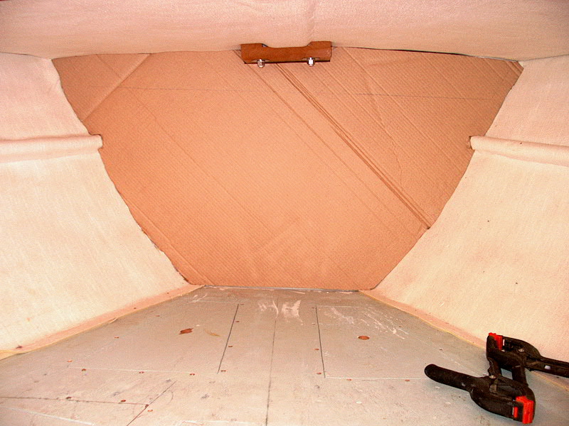 vee
berth. One of the advantages to cardboard is that you can easily cut and
modify it on the fly, so I figured it would be easier to create these notches on
the boat. vee
berth. One of the advantages to cardboard is that you can easily cut and
modify it on the fly, so I figured it would be easier to create these notches on
the boat.
Once I relieved the cardboard by notching it
around the stiffeners, it slipped nicely--and tightly--into place. No
further modifications were necessary. I think it all looks better
already! Before removing the template for the last time, I used a framing
square to mark a straight line parallel to and 1-1/2" above the surface of
the vee berth, and, still using the square, drew a vertical line up as
well. These will provide useful reference when the time comes to lay out
and cut the actual plywood bulkhead and the opening therein.
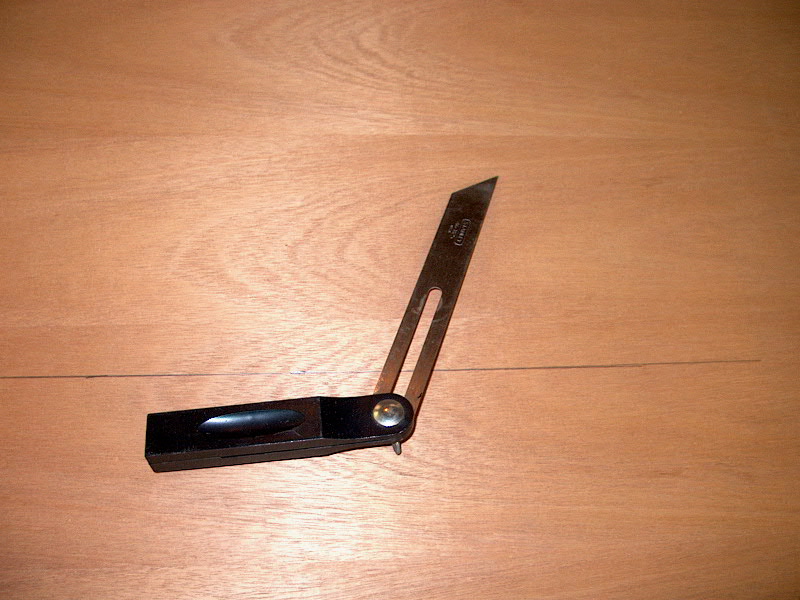
 I
finished preparation by measuring the angle at which the hull meets the bulkhead
in a longitudinal direction. I used a bevel gauge to get this angle, which
turned out to be about 30º. This angle is important because the face side
of the new bulkhead must actually be slightly wider than the template to
compensate for the broadening of the hull. I
finished preparation by measuring the angle at which the hull meets the bulkhead
in a longitudinal direction. I used a bevel gauge to get this angle, which
turned out to be about 30º. This angle is important because the face side
of the new bulkhead must actually be slightly wider than the template to
compensate for the broadening of the hull.
After a few days' waiting, my wood order was
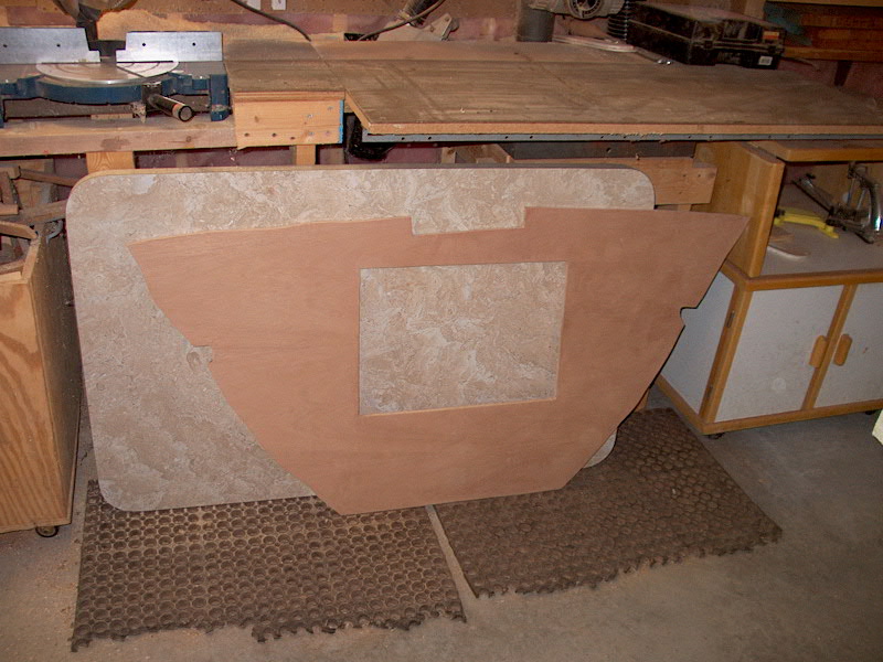
delivered, and I got back to work. I laid out the cardboard template on a
piece of 1/2" Honduras mahogany plywood and traced the outline.
Because the actual face of the plywood bulkhead must be wider than the
template--for the reasons described above--I laid the template out upside down
on the back side of the plywood. This means that the angled cut will be
wider on the face side than the back. I set my jigsaw blade to match the
bevel gauge at 30º and cut out the sides of the new bulkhead. I made the
top and bottom cuts with the blade set vertically, since no angle was required.
With the new bulkhead cut out, the next step
was to create the opening in the bulkhead for future access to the chain
locker. Using some marks I had placed on my original paper pattern, I laid
out the opening, taking into account the position of the existing partial
bulkhead and ensuring that the new opening was large enough to actually fit
through if I need to crawl partially in there to access anything. Before
making the cut, though, I tested the fit of the bulkhead on the boat. The
fit was pretty good, although the gaps in a couple places were a little wider
than I would have liked. I was hoping for a tight fit all around to
minimize the need for trim pieces. Unfortunately, the hull shape just
isn't necessarily consistent over the 1/2" thickness of the plywood, and
slight variations from the tight-fitting pattern occurred. In particular,
my cut on the port side to accommodate the stiffener in the hull was poorly
done, and I was upset with this. I can cover the seams with trim, but I
was really hoping for a better fit. Remember, this bulkhead serves no
structural purpose, and will not be tabbed into the hull. If I had built
it earlier in the restoration process, I probably would have tabbed it to the
hull just for good measure, and the tabbing would cover any of the small gaps
that I now have to deal with. Of course, then I would have had to find a
way to hide the ugly tabbing, so I guess I'm not really any worse off. In
any case, none of the gaps were wide enough to call for cutting a new piece of
plywood. Trim will successfully cover all later in the process. In
order to get the bulkhead pulled back away from its test position, I inserted a
couple screws into the section I plan to cut out for the opening.
|
|
 Once
I was satisfied with the fit, I returned to my shop and cut out the opening with
my jigsaw. The opening is 18" wide by 13" high (I think, if
memory serves). I located it high enough so that the bottom is just
about even (a little higher) with the cutout on the existing bulkhead. I
couldn't make it much wider than I did because I didn't want to remove much of
the existing bulkhead--I'd prefer to keep the structure intact. (See the
photo at the top of the page for the existing configuration.) Once
I was satisfied with the fit, I returned to my shop and cut out the opening with
my jigsaw. The opening is 18" wide by 13" high (I think, if
memory serves). I located it high enough so that the bottom is just
about even (a little higher) with the cutout on the existing bulkhead. I
couldn't make it much wider than I did because I didn't want to remove much of
the existing bulkhead--I'd prefer to keep the structure intact. (See the
photo at the top of the page for the existing configuration.)
I also cut two Okoume 1088 plywood beams, cut
to the same template shape, for installation forward of the existing
bulkhead. Actually, one will be inserted flush with the cutout at the top,
and the other will be directly forward of that. These two pieces will be epoxied
together, to the existing bulkhead, and to the underside of the deck to help
stiffen the foredeck and also help support the top of the new cosmetic mahogany
bulkhead. Installation of these structural pieces is imminent, depending
on whether the silly abnormal high daytime temperatures continue. (40's
and even 50's in February...consistently! Wassup widdat?)
With the bulkhead all cut out and ready for
finish and installation, I moved on to building a hatch to close off the
opening. With the bulkhead still in my shop, it was the perfect
opportunity to save a number of trips back and forth to the boat for measuring
and fitting.
|
|
 The first thing I had to do, however, was deal
with my rough mahogany lumber. I had ordered my mahogany dimensioned on
three sides (D3S), since I don't have a thickness planer. D3S means that
the rough 4/4 stock is planed down to its finished thickness of 3/4", and
one edge is jointed smooth. The day before my delivery was scheduled, I
received an apologetic call from the supplier with the news that they no longer
stocked finished lumber, and that unless I wanted to pay a steep price for
planing, I would receive the mahogany in the rough state. (The cherry I
ordered came properly planed D3S.) I elected to go ahead with the rough
stuff and deal with smoothing it afterwards. The first thing I had to do, however, was deal
with my rough mahogany lumber. I had ordered my mahogany dimensioned on
three sides (D3S), since I don't have a thickness planer. D3S means that
the rough 4/4 stock is planed down to its finished thickness of 3/4", and
one edge is jointed smooth. The day before my delivery was scheduled, I
received an apologetic call from the supplier with the news that they no longer
stocked finished lumber, and that unless I wanted to pay a steep price for
planing, I would receive the mahogany in the rough state. (The cherry I
ordered came properly planed D3S.) I elected to go ahead with the rough
stuff and deal with smoothing it afterwards.
I do own a jointer, although I hadn't used it
for years. The jointer has always been the most frustrating tool in my
shop. I find setting it properly so that it makes the right cut is nearly
impossible; this problem is probably compounded by the fact that it's an
inexpensive model, which are notoriously difficult to set up. Add in the
long periods of neglect between use attempts, and success seems impossible.
However, I thought I would give it a
try. It has a six-inch blade, so it was wide enough to deal with the
pieces I had to smooth. I spent some time cleaning it up, and setting it
up in what appeared to be the proper way. However, as I began running the
boards through, it was obvious that the setup was off. I was getting
tapered cuts--thicker at one end and virtually nothing at the other. I
tried fine tuning the tables for a while, but soon got sick of it and gave up
yet again. Anyone want a cheap jointer?
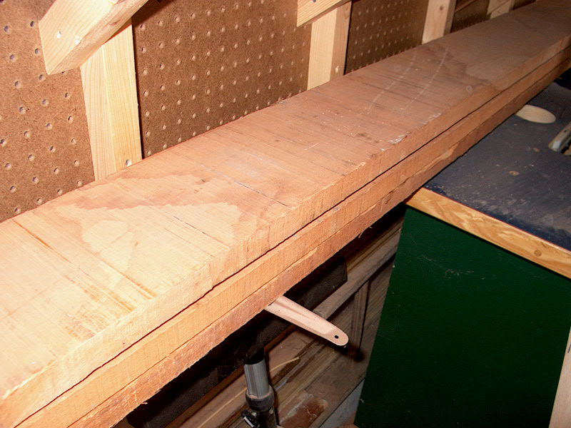
I decided to simply use my table saw to resaw
the boards and cut them to the proper thickness of 3/4". Fortunately,
the rough edges of the boards were straight enough that I could use one as a
guide to rip a small amount off the opposite edge. Then, by turning the
board around, I placed the now-smooth edge against the saw fence and trimmed the
rough board to a little wider than the desired width. Because the board I
was using featured some bends in it, I cut off a piece a little longer than I
needed before continuing. The shorter piece was flat over its length,
making further cuts more accurate. Raising the blade on the saw as high as
it would go, and setting the fence to just about an inch away from the blade, I
carefully ran the board through on edge. The saw blade made a pretty
smooth cut as I pushed the board through, although the full height of the blade
wasn't quite enough to get through the whole board. I had to turn the
board around and make another pass to complete the cut.
With one side resawn, I turned the board
around, set the fence to a hair over 3/4", and repeated the process on the
other face. I ended up with a fairly smooth board of the proper thickness;
the table saw cut is a whole lot smoother than the rough cut was, and should be
easy to sand smooth later in the process. If this were oak instead of
mahogany, this entire process would have been substantially more difficult, if
not infeasible. Fortunately, mahogany mills beautifully. I only did
this to enough stock for the jobs immediately at hand--but I still have 3
unfinished boards that are about 8" wide by 8 feet long that I'll have to
deal with. Maybe I'll take them to a local shop for planing. The
whole process I described took quite a bit of time.
With the stock prepared to rough dimensions, I
moved on to milling the rails and stiles for my hatch into the chain
locker. As with the other doors on the interior, I milled the pieces to
1-1/2" width, and sized their lengths to accommodate a standard 3/8"
overlay on the cabinet. I decided on a single door--I'm not yet sure if
I'm going to hinge it on the bottom or on one side. Originally, I had
planned on two doors meeting in the middle. However, I realized that I had
not milled enough of the mahogany down to the proper thickness (as described
above), since I had only taken the dimensions of the rough opening into account,
and failed to account for the extra rails in the middle that would be required
for a pair of doors. I didn't want to repeat the dimensioning process, so
I decided upon one door. The opening is only 18" x 13" anyway,
so it's not as if the single door will be way too big.
|
|
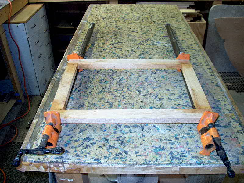 With
the four pieces for the door frame cut, I mixed up a small batch of thickened
epoxy. Because of the strength of the epoxy, I am relying only on butt
joints for the corners--no fancy joinery. In other instances I find it
desirable to create a stronger joint at the corners, but haven't found it
necessary on the doors for the boat--the epoxy is simply strong enough that the
butt joints seem to work well. They certainly take less time to
create. I glued up the door frame and clamped it securely to sit overnight
before continuing. With
the four pieces for the door frame cut, I mixed up a small batch of thickened
epoxy. Because of the strength of the epoxy, I am relying only on butt
joints for the corners--no fancy joinery. In other instances I find it
desirable to create a stronger joint at the corners, but haven't found it
necessary on the doors for the boat--the epoxy is simply strong enough that the
butt joints seem to work well. They certainly take less time to
create. I glued up the door frame and clamped it securely to sit overnight
before continuing.
With that out of the way, I decided to go
ahead with installing the new deck beams at the chain locker. The weather
was warm enough to support epoxy. Before going ahead, I took the two
plywood pieces up to the boat and checked the fit. There were a few gaps,
but nothing serious. Really, this beam's structural purpose is extremely
limited. I see no reason to make this thing bulletproof. The boat
does not need the structure; it's really there to just minimize some of the flex
that naturally occurs in the wide foredeck. Therefore, I won't be spending
hours and hours honing the fit to perfection, and glassing it in place with
multiple layers of cloth. This seems completely unnecessary to me for this
application. Plus, with the finished surfaces of the vee berth (including
the fabric liner), creating proper tabbing is not possible without destroying
the fabric. In hindsight, I suppose I should have installed this beam at
an early stage of the project. But, considering that it is really
unnecessary from any structural standpoint, I think just epoxying it in place
with a thick mixture will be more than sufficient and will add that additional
support to the foredeck.
|
|
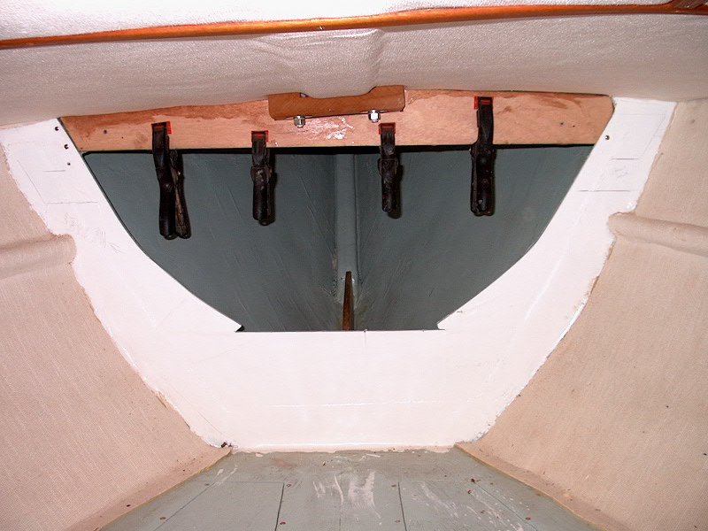 Once
I was satisfied with the fit of the two pieces--one goes just forward of the
existing bulkhead, the other fits flush in between the cutout at the top--I
mixed up a pretty large batch of very thick epoxy, using 406 colloidal
silica. Then, up at the boat, I applied the mixture to the top edge of the
forwardmost plywood beam, and clamped it up in place. pressing the beam into the
thick band of epoxy. I then coated the facing side of the beam with more
epoxy, layered more on top of the second beam, and clamped that one in place as
well. To help secure the two beams, I drove some stainless steel screws as
necessary to augment the clamps. The screws will stay in place in the
completed installation. I cleaned up the excess epoxy and filled any small
gaps with the remaining mixture. I left the beams clamped for a couple
days. Again: remember that even though the beam looks
crooked in the photo, the bottom edge is level and parallel with the vee berth
and bulkhead cutout. It's just the foredeck above that is out of
whack. I think it was molded this way originally. Once
I was satisfied with the fit of the two pieces--one goes just forward of the
existing bulkhead, the other fits flush in between the cutout at the top--I
mixed up a pretty large batch of very thick epoxy, using 406 colloidal
silica. Then, up at the boat, I applied the mixture to the top edge of the
forwardmost plywood beam, and clamped it up in place. pressing the beam into the
thick band of epoxy. I then coated the facing side of the beam with more
epoxy, layered more on top of the second beam, and clamped that one in place as
well. To help secure the two beams, I drove some stainless steel screws as
necessary to augment the clamps. The screws will stay in place in the
completed installation. I cleaned up the excess epoxy and filled any small
gaps with the remaining mixture. I left the beams clamped for a couple
days. Again: remember that even though the beam looks
crooked in the photo, the bottom edge is level and parallel with the vee berth
and bulkhead cutout. It's just the foredeck above that is out of
whack. I think it was molded this way originally.
|
|
Please click here to
continue the project. |
|