|
Electrical
Distribution and Wiring
This page was last updated on 2 June 2001
For several days, I have been pulling wires for most of the
electrical fixtures on the boat. We have 10 cabin lights, running lights
fore and aft, masthead and steaming lights, and a propane solenoid to worry
about, as well as the electric bilge pump and stereo. It's amazing how
long it takes to prepare for and feed wires throughout the boat!
|
 First,
I decided on where I wanted to make the main wiring runs. The electrical
panel is on the port side, forward of the icebox. I decided to run the
wired strung beneath the shelf at the top of the settee backs on each side, as
this location will be the least susceptible to damage. To begin, I drilled
a series of large holes--several into the bottom of the area beneath the
electrical locker, and through each bulkhead and other obstruction on the way
forward. On the port side, this was easy, and the wiring takes a pretty
direct route. To get to the starboard side, however, I had to run wires
along the top of the icebox countertop (I have left this area free of cabinets
for now, and will install a wire chase and cabinets when the wiring is done),
down in front of the cockpit (through two lengths of hose that act as wire
chases) and then across the front of the cockpit inside the engine room.
The starboard side wires then run through the galley cabinets, and finally up
behind the starboard settee. To support the wiring bundles, I installed
plastic wire ties every foot or so as needed, screwed into the underside of the
cabinets and countertops above, and also lines each hole through the bulkheads
with a short length of clear vinyl hose to protect against chafe. For the
running lights, I continued the wire supports and lined holes up to the chain
locker forward and through the cockpit locker to the lazarette aft. This
process took a lot longer than you might think, especially hanging the wire
ties--in some areas, the access was blind and quite tight, so it often took
several tries to even get the screw started. I looped the each wire tie
loosely together to support the wires during installation; later, when
everything is done, I'll go back and tighten each tie and neaten the wire
bundles as necessary. The wires shown above will be pulled close to each
side of the space, once the wire ties are pulled tight. First,
I decided on where I wanted to make the main wiring runs. The electrical
panel is on the port side, forward of the icebox. I decided to run the
wired strung beneath the shelf at the top of the settee backs on each side, as
this location will be the least susceptible to damage. To begin, I drilled
a series of large holes--several into the bottom of the area beneath the
electrical locker, and through each bulkhead and other obstruction on the way
forward. On the port side, this was easy, and the wiring takes a pretty
direct route. To get to the starboard side, however, I had to run wires
along the top of the icebox countertop (I have left this area free of cabinets
for now, and will install a wire chase and cabinets when the wiring is done),
down in front of the cockpit (through two lengths of hose that act as wire
chases) and then across the front of the cockpit inside the engine room.
The starboard side wires then run through the galley cabinets, and finally up
behind the starboard settee. To support the wiring bundles, I installed
plastic wire ties every foot or so as needed, screwed into the underside of the
cabinets and countertops above, and also lines each hole through the bulkheads
with a short length of clear vinyl hose to protect against chafe. For the
running lights, I continued the wire supports and lined holes up to the chain
locker forward and through the cockpit locker to the lazarette aft. This
process took a lot longer than you might think, especially hanging the wire
ties--in some areas, the access was blind and quite tight, so it often took
several tries to even get the screw started. I looped the each wire tie
loosely together to support the wires during installation; later, when
everything is done, I'll go back and tighten each tie and neaten the wire
bundles as necessary. The wires shown above will be pulled close to each
side of the space, once the wire ties are pulled tight.
|
|
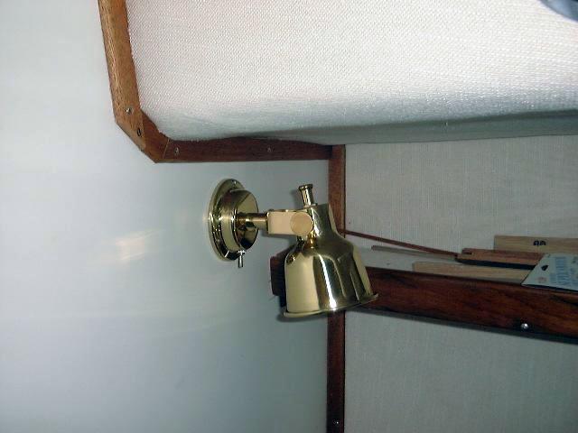
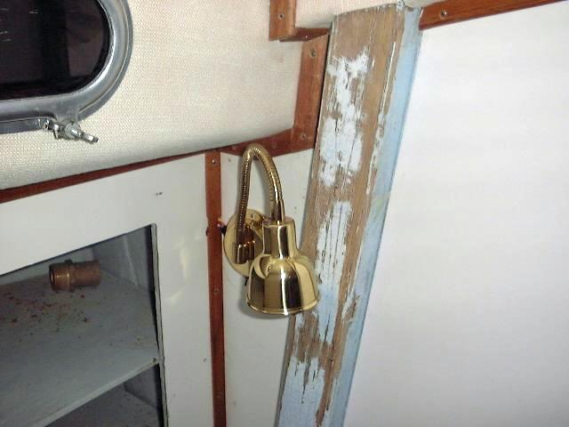
 The
next step was to figure out where the various fixtures would be located. I
placed two different kinds of lamps: halogen reading lamps, and halogen
gooseneck lamps. There's a reading lamp on each side of the vee berth and
one for each settee in the main cabin. We're planning full bookshelves
along the starboard bulkhead in the inset area, so no fixtures went there.
I installed a gooseneck on each side of the head The
next step was to figure out where the various fixtures would be located. I
placed two different kinds of lamps: halogen reading lamps, and halogen
gooseneck lamps. There's a reading lamp on each side of the vee berth and
one for each settee in the main cabin. We're planning full bookshelves
along the starboard bulkhead in the inset area, so no fixtures went there.
I installed a gooseneck on each side of the head  compartment
(by the way, I can't wait to paint those ugly oak beams!), and another two on
either side of the salon, in the middle portion of the upper cubbyholes. A
final two went aft above the galley, one on each side. With the fixture
locations pegged, I began running the wires to them as necessary, keeping the
wires hidden as best as possible. I had to run some exposed wires in a
couple areas--there was just no way to avoid it, but the
exposure is minimal I'll cover them with small raceways soon. I was
planning on installing a red/white fluorescent fixture above the stove, compartment
(by the way, I can't wait to paint those ugly oak beams!), and another two on
either side of the salon, in the middle portion of the upper cubbyholes. A
final two went aft above the galley, one on each side. With the fixture
locations pegged, I began running the wires to them as necessary, keeping the
wires hidden as best as possible. I had to run some exposed wires in a
couple areas--there was just no way to avoid it, but the
exposure is minimal I'll cover them with small raceways soon. I was
planning on installing a red/white fluorescent fixture above the stove,  but I
discovered it was not ignition protected, and thought it would be a bad idea
with LPG. At each fixture, I connected the wires with crimped heat shrink
Ancor butt connectors, shrinking the casing with a small torch. I left
some excess wire bundles in the base of each fixture for ease of servicing
later. I marked each set of wires with its destination in preparation for
more permanent labeling later. but I
discovered it was not ignition protected, and thought it would be a bad idea
with LPG. At each fixture, I connected the wires with crimped heat shrink
Ancor butt connectors, shrinking the casing with a small torch. I left
some excess wire bundles in the base of each fixture for ease of servicing
later. I marked each set of wires with its destination in preparation for
more permanent labeling later.
|
|
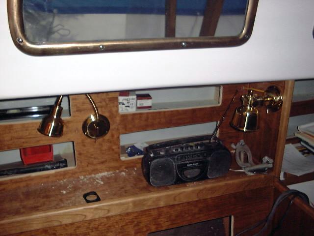
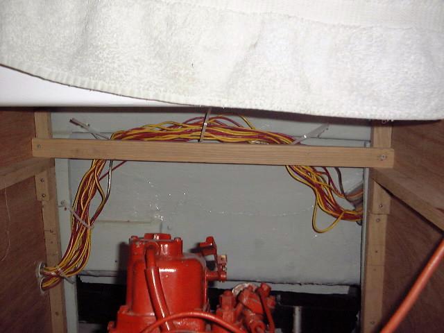
I ran wires up the starboard side for the
masthead and steaming lights (separate circuits), and also for a 12-volt outlet
I installed in the head. I think we are planning on a deck box-type
propane cylinder locker either near the mast or on the foredeck, so I ran the
wires for the solenoid up as far as the head. These three circuits are
dead ended for now until I decide how to arrange the final connections to the
above deck fixtures they supply. I also ran speaker wires to the stereo
speakers in the main bulkhead.
This makes for a lot of wires! I used
Ancor 14 ga. tinned wire in red and yellow for most circuits (yellow is often
preferred for DC ground wires). For the running lights, I used 12 ga.
tinned wire, since the wiring runs are significantly longer. Plus, I had
it on hand. I also ran three lengths of the 12 ga. down to the bilge for
the automatic bilge pump, which I will install later.
|
|
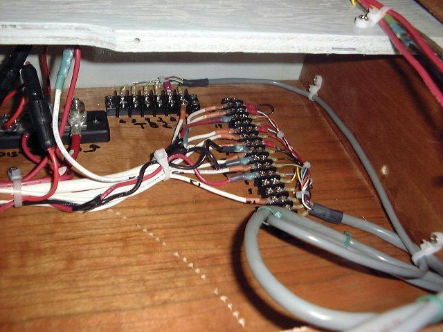
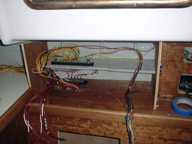 With
the mass or wires exiting from the back of the electrical locker, I began the
process of sorting and connecting. I installed a large bus block for the
ground wires, and connected all the grounds to the block after running them
through wire ties to keep the runs neat and organized. Then, I installed
heat shrink wire ID labels near the end of each positive wire--each is labeled
with a number, which I recorded on a pad for now; later, I'll make a permanent
list of the circuits and a diagram. I attached all the positive leads from
the cabin lights to a bus block, which will allow me to connect all 10 lights to
a single 20-amp circuit breaker with a single wire. I cut the other leads
to length and installed ring connectors in preparation for wiring to the
distribution panel. This is how it stands now. Again, I will
be neatening all the bundles when all the wiring is run, but I want to leave the
wire tie loops loose for now in case I find other wires to run. I have
bundled certain circuits together where possible, like the stereo wires (seen to
the right), the running lights, and bilge pump wires. With
the mass or wires exiting from the back of the electrical locker, I began the
process of sorting and connecting. I installed a large bus block for the
ground wires, and connected all the grounds to the block after running them
through wire ties to keep the runs neat and organized. Then, I installed
heat shrink wire ID labels near the end of each positive wire--each is labeled
with a number, which I recorded on a pad for now; later, I'll make a permanent
list of the circuits and a diagram. I attached all the positive leads from
the cabin lights to a bus block, which will allow me to connect all 10 lights to
a single 20-amp circuit breaker with a single wire. I cut the other leads
to length and installed ring connectors in preparation for wiring to the
distribution panel. This is how it stands now. Again, I will
be neatening all the bundles when all the wiring is run, but I want to leave the
wire tie loops loose for now in case I find other wires to run. I have
bundled certain circuits together where possible, like the stereo wires (seen to
the right), the running lights, and bilge pump wires.
|
|
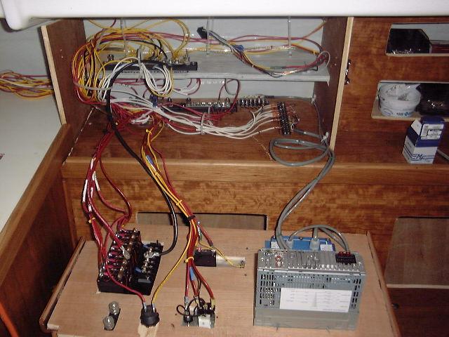
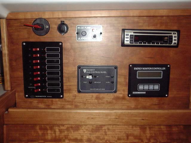 The
main distribution panel is a Marinetics 8-breaker panel, with breaker amperages
ranging from 5 to 20 amps. It is a nice compact, basic panel, seen on the
left side of the photo. Above it is the emergency starter battery
parallel switch, then, moving right, a 12 volt outlet, bilge pump switch and
fuse, and the stereo. On the lower level is the propane solenoid control
panel and, on the far right, the Ample Power energy monitor. The panel is
connected to the positive and negative distribution buses with short lengths of
#8AWG cable; the feeds from the main positive and negative distribution posts,
located in the engine room, are #2 battery cable. The
main distribution panel is a Marinetics 8-breaker panel, with breaker amperages
ranging from 5 to 20 amps. It is a nice compact, basic panel, seen on the
left side of the photo. Above it is the emergency starter battery
parallel switch, then, moving right, a 12 volt outlet, bilge pump switch and
fuse, and the stereo. On the lower level is the propane solenoid control
panel and, on the far right, the Ample Power energy monitor. The panel is
connected to the positive and negative distribution buses with short lengths of
#8AWG cable; the feeds from the main positive and negative distribution posts,
located in the engine room, are #2 battery cable.
I began to make final connections between the
wiring and the distribution panel, at least for the circuits I have run. I
still have to run power feeds for a GPS, knotmeter/depthsounder, and VHF radio,
but these will come a little bit later. First, I connected all the
negative wires to a 20-position bus block I installed on the shelf inside the
cabinet. I joined two wires together inside a single ring conductor,
heat-shrunk each, and fastened them down. I made the connection from the
bus to the negative distribution on the panel with a length of 8 gauge wire.
|
|
 I
attached the positive leads to the appropriate breakers on the panel, picking an
amperage rating that closely matched the expected loads on the circuits, I
also wired the new bilge pump switch and propane control panel. Next, I
screwed down the two terminal blocks (attached to the gray-sheathed cables on
the right side of the box in the photo) that came with the energy monitor, and
began making up those connections according to the wiring diagrams.
This necessitates a fair number of wires, and it's still not done. Each
wire requires running it wherever it needs to go through the convoluted wire
chases, cutting to length, stripping the insulation from each end, crimping on
the appropriate connector at each end, heat-shrinking each connector, and,
finally, attaching the connector to the terminal. It's amazing how long
this takes. Doing a neat, clean job also extends the whole process, and it
still looks like a rat's nest--at least for now. Once all the wires are
run, I will tighten all the cable clamps and neaten the wire bundles.
There is rhyme and reason to how everything is run! I
attached the positive leads to the appropriate breakers on the panel, picking an
amperage rating that closely matched the expected loads on the circuits, I
also wired the new bilge pump switch and propane control panel. Next, I
screwed down the two terminal blocks (attached to the gray-sheathed cables on
the right side of the box in the photo) that came with the energy monitor, and
began making up those connections according to the wiring diagrams.
This necessitates a fair number of wires, and it's still not done. Each
wire requires running it wherever it needs to go through the convoluted wire
chases, cutting to length, stripping the insulation from each end, crimping on
the appropriate connector at each end, heat-shrinking each connector, and,
finally, attaching the connector to the terminal. It's amazing how long
this takes. Doing a neat, clean job also extends the whole process, and it
still looks like a rat's nest--at least for now. Once all the wires are
run, I will tighten all the cable clamps and neaten the wire bundles.
There is rhyme and reason to how everything is run!
|
|
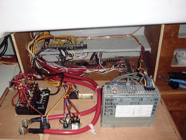
With the bulk of the regular wiring complete,
including all the connections on the battery monitor and regulator, I moved on
to running some heavy battery cable according to my wiring schematic. The
installation calls for several of the feeds to be 2/0 cable, which is heavy,
expensive stuff to work with. I did not enjoy it. Working with such
heavy cable requires some special tools, including a pair of heavy duty wire
cutters and a lug crimping tool. I ran the heavy wire as called for and
crimped on the copper lugs, protecting each connection with heat shrink
tubing. This cable is probably overkill for the expected loads on this
boat, but it was called for in the schematic, and I'd rather have cable that is
too large rather than too small. At least I know my starter will always
have plenty of juice and not be affected by voltage drop! There are also
several runs of #2 battery cable, again wired as called for in the
diagram. Click here
to view a copy of the wiring schematic for the system I am installing
I recommend it in order to get a better idea of the sheer number of wires
involved.
|
|
 After
several partial days struggling with working with the heavy 2/0 cable, I finally
attached the last piece of the miserable stuff. This completed the bulk of
the wiring, with only a half dozen or so #2 AWG wires remaining to run,
including the starter and alternator wires. Before tightening all the tie
wraps on the wiring bundles in and around the service panel, I ran a few last
pair of wires for the compass light, GPS power feed, VHF radio, and to the
knotmeter/depthsounder. I couldn't think of any other wires to run for the
planned equipment, so I called it good. I spent some time neatening the
bundles behind the main service panel, and tightening the tie wraps to pull
everything into place. Finally, it looked a little more organized and less
like a rat's nest. In the photo, you can see that the wire bundles have
been pulled tightly together, and also see the 2/0 battery cable snaking its way
up to the emergency parallel battery switch on the left. I wired enough
slack into the panel to allow the whole thing to be removed and laid flat like
you see in the photo, allowing for easy maintenance and addition of extra wires
later. After
several partial days struggling with working with the heavy 2/0 cable, I finally
attached the last piece of the miserable stuff. This completed the bulk of
the wiring, with only a half dozen or so #2 AWG wires remaining to run,
including the starter and alternator wires. Before tightening all the tie
wraps on the wiring bundles in and around the service panel, I ran a few last
pair of wires for the compass light, GPS power feed, VHF radio, and to the
knotmeter/depthsounder. I couldn't think of any other wires to run for the
planned equipment, so I called it good. I spent some time neatening the
bundles behind the main service panel, and tightening the tie wraps to pull
everything into place. Finally, it looked a little more organized and less
like a rat's nest. In the photo, you can see that the wire bundles have
been pulled tightly together, and also see the 2/0 battery cable snaking its way
up to the emergency parallel battery switch on the left. I wired enough
slack into the panel to allow the whole thing to be removed and laid flat like
you see in the photo, allowing for easy maintenance and addition of extra wires
later.
|
|
 These
are the terminal blocks containing the various sensor wires for the Ample Power
energy monitor. These
are the terminal blocks containing the various sensor wires for the Ample Power
energy monitor.
|
|
 This
is one of the auxiliary positive distribution feeds, with length of 2/0 cable
running from the engine room. This
is one of the auxiliary positive distribution feeds, with length of 2/0 cable
running from the engine room.
|
|
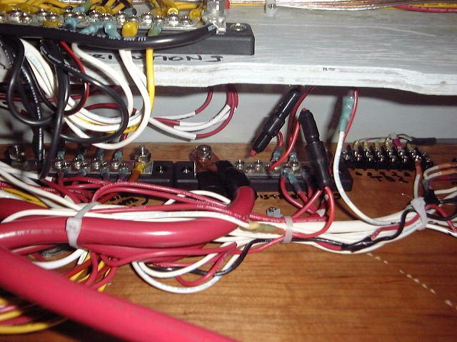
 This
is the negative distribution bus block, located behind the main service
panel. All ground wires from the lights and other appliances are
terminated here. This
is the negative distribution bus block, located behind the main service
panel. All ground wires from the lights and other appliances are
terminated here.
|
|
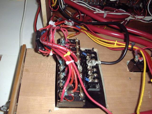
 This
is the back of the circuit breaker panel. This
is the back of the circuit breaker panel.
|
|
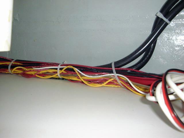
 This
is the wiring bundle leading aft from behind the service panel, outboard of the
icebox. It contains three lengths of the 2/0 cable. This bundle will
eventually be hidden by a cherry panel that I will install later, which will
also hide the inside of hull. This
is the wiring bundle leading aft from behind the service panel, outboard of the
icebox. It contains three lengths of the 2/0 cable. This bundle will
eventually be hidden by a cherry panel that I will install later, which will
also hide the inside of hull.
|
|
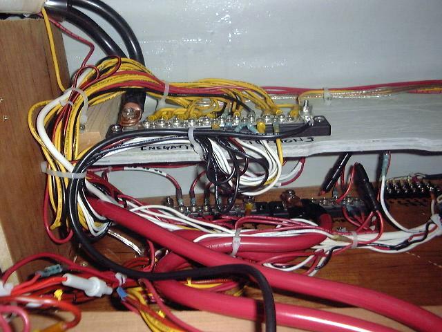
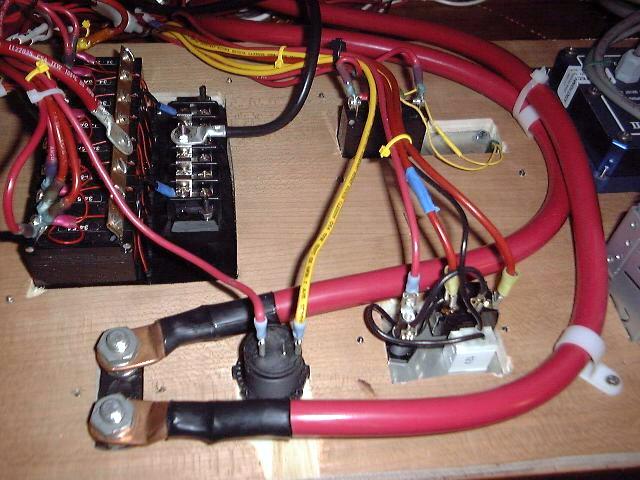
 This
is the wiring (2/0 cable) to the back of the battery switch on the main
panel. This switch is designed only as an emergency parallel switch to
allow the house battery bank to be used to start the engine in case anything
should happen to the starting battery. Check out the wiring
schematic for an understanding into the principles here. This
is the wiring (2/0 cable) to the back of the battery switch on the main
panel. This switch is designed only as an emergency parallel switch to
allow the house battery bank to be used to start the engine in case anything
should happen to the starting battery. Check out the wiring
schematic for an understanding into the principles here.
There is extra room on the circuit breaker
panel at the moment, so there is room to grow. There is also more room on
the shelf behind the service panel for additional terminal blocks or bus blocks
if they should be necessary later.
After running a few lengths of #2 battery
cable to the starter solenoid and alternator, the wiring was pretty much complete.
Over the period of time between finishing the bulk wiring and launching, I took
care of a few minor details and additional wiring projects. Before the
wiring is complete, I intend to install sound insulation in the engine room;
this will require rebundling a few of the wires, so I don't have completed
photos yet. I expect this project to occur within the next several weeks.
Other electrical system information can be found on the battery
page and the charging page on this site.
|
|