|
Propane Stove &
Fuel System
This page was last updated on 24
March 2002.
Stove and Basic
Installation Gas
Control Panel Installation
LPG Tank,
Regulator, and Solenoid Installation
LPG Vapor Sniffer and Alarm System Installation
|
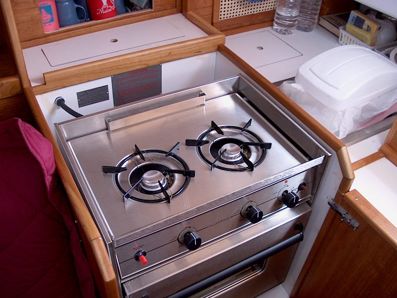
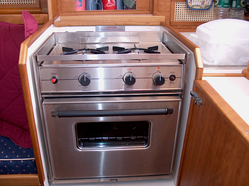
 With the cabinetry around the stove and galley
done, and the stove (which had been stored in the head since August) generally
in the way, I decided to turn to the installation in its proper place.
Previously, I built a cabinet for the stove--more of an alcove, really, with
dimensions based on the size required for the unit. The stove is a Seaward
Hillerange 2-burner with oven. With the cabinetry around the stove and galley
done, and the stove (which had been stored in the head since August) generally
in the way, I decided to turn to the installation in its proper place.
Previously, I built a cabinet for the stove--more of an alcove, really, with
dimensions based on the size required for the unit. The stove is a Seaward
Hillerange 2-burner with oven. |
|
 To install the gimbaled stove, I first cut a
paper pattern of the side of the stove, with the gimbal point clearly parked,
and test fit it on the side of the alcove, swinging it to and fro to see how far
it would go without hitting any obstructions. I moved it around until I
felt I had found the proper place, and marked the gimbal center. I transferred
the measurement to the other side in preparation for installing the gimbal
brackets. I bolted these brackets to the cabinets with #10 machine screws;
I had to use bolts since screws would have penetrated the 1/2" plywood
enclosure. Then, it was a matter of lifting the stove into the brackets,
which are equipped with clips that prevent the stove from jumping up out of the
brackets. To install the gimbaled stove, I first cut a
paper pattern of the side of the stove, with the gimbal point clearly parked,
and test fit it on the side of the alcove, swinging it to and fro to see how far
it would go without hitting any obstructions. I moved it around until I
felt I had found the proper place, and marked the gimbal center. I transferred
the measurement to the other side in preparation for installing the gimbal
brackets. I bolted these brackets to the cabinets with #10 machine screws;
I had to use bolts since screws would have penetrated the 1/2" plywood
enclosure. Then, it was a matter of lifting the stove into the brackets,
which are equipped with clips that prevent the stove from jumping up out of the
brackets.
Next, I drilled a hole in the cabinet opposite
the gimbal lock lever and installed the supplied cover plate. This
completed the physical installation of the stove unit itself.
|
|
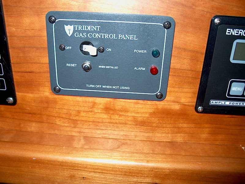 At
this stage, I also installed a Trident solenoid control panel in the
electrical panel across from the stove. This panel features its own
circuit breaker and indicator light. At the time I purchased the panel,
the s tore did not have one with integral alarm in stock, so I bought the
regular panel. It can be upgraded to include a sniffer, alarm, and auto
shutoff, which I will do a little later. At
this stage, I also installed a Trident solenoid control panel in the
electrical panel across from the stove. This panel features its own
circuit breaker and indicator light. At the time I purchased the panel,
the s tore did not have one with integral alarm in stock, so I bought the
regular panel. It can be upgraded to include a sniffer, alarm, and auto
shutoff, which I will do a little later.
Installing the Trident panel was
a matter of cutting an appropriate hole in my wooden panel, and screwing the
panel into place. Then, I ran a pair of wires (red and yellow) from the
back of the panel, behind the engine, and along the starboard side of the hull,
following my existing wiring runs, and dead-ending the wires in the head, where
I would eventually create a final run up to the propane solenoid, when
installed. However, at this point (February 2001), I had bigger fish
to fry, so to speak, as I rushed to get the boat ready for launch.
Completing the LPG installation would have to wait until later.
Update--July
2001
Well, it took nearly two months after
launching the boat to finally get the propane tank and hoses installed!
Working with the engine and other projects--plus enjoying the boat and
sailing--meant that my timeframe got delayed somewhat. Plus, the fact that
I didn't have a clear idea how I was going to install the tank meant that I
tended to procrastinate on starting the job.
My initial thought, way back when, had been to
install a dedicated locker in the lazarette. However, after cutting the
hole and sizing things up, it seemed to be a complicated proposal--and it would
eat up all the valuable storage space in the lazarette. After having the
boat in the water for awhile, it was obvious that I didn't want to give up this
space.
The next thought was to build a deck box to
hold the tank and secure it somewhere on the deck, perhaps by the mast or on the
foredeck. This simplifies matters because, with the tank essentially open
to the atmosphere abovedecks, many of the critical safety considerations are
eliminated, since the gas, if it were to leak, would just blow overboard rather
than collect somewhere in the bilges, as it would with a belowdecks tank.
I went forward with this plan, and built a nice mahogany box for the tank (a
horizontal 10-lb. aluminum tank). I varnished it up nicely, and finally
was ready to try it on the boat.
|
|
 An
ideal place for this box would have been behind the mast, immediately forward of
the bump in the cabin trunk. Unfortunately, on my boat I installed a solid
boom vang that cuts into this space; I was certainly not going to give up the
vang for the sake of propane storage. I had thought that maybe the box
would fit to either side of the mast, but this didn't work either. The
foredeck, just forward of the cabin trunk, had potential, but it definitely took
up more room than ideally desired, and I worried a little about genoa sheets
catching on the box. An
ideal place for this box would have been behind the mast, immediately forward of
the bump in the cabin trunk. Unfortunately, on my boat I installed a solid
boom vang that cuts into this space; I was certainly not going to give up the
vang for the sake of propane storage. I had thought that maybe the box
would fit to either side of the mast, but this didn't work either. The
foredeck, just forward of the cabin trunk, had potential, but it definitely took
up more room than ideally desired, and I worried a little about genoa sheets
catching on the box.
|
|
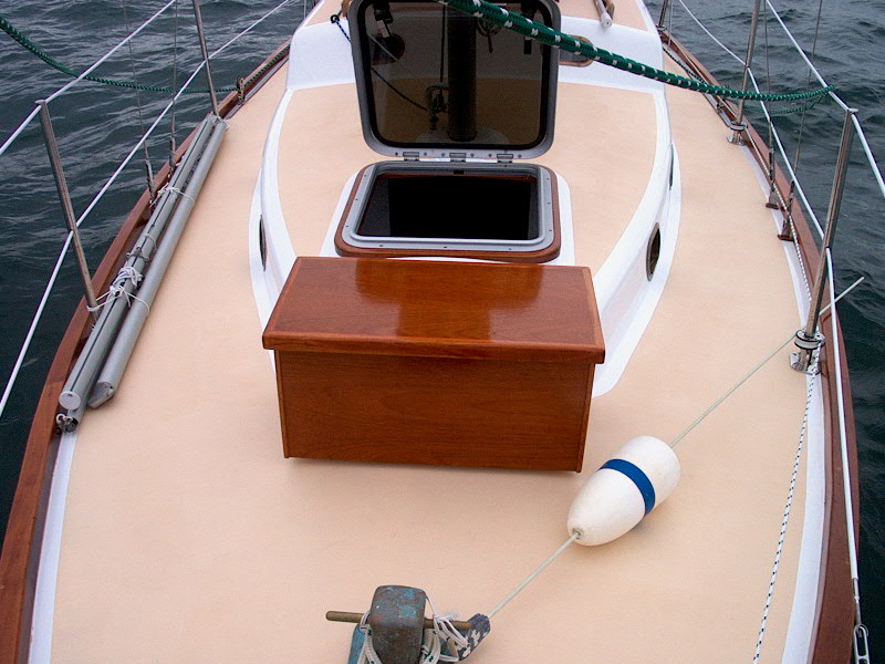
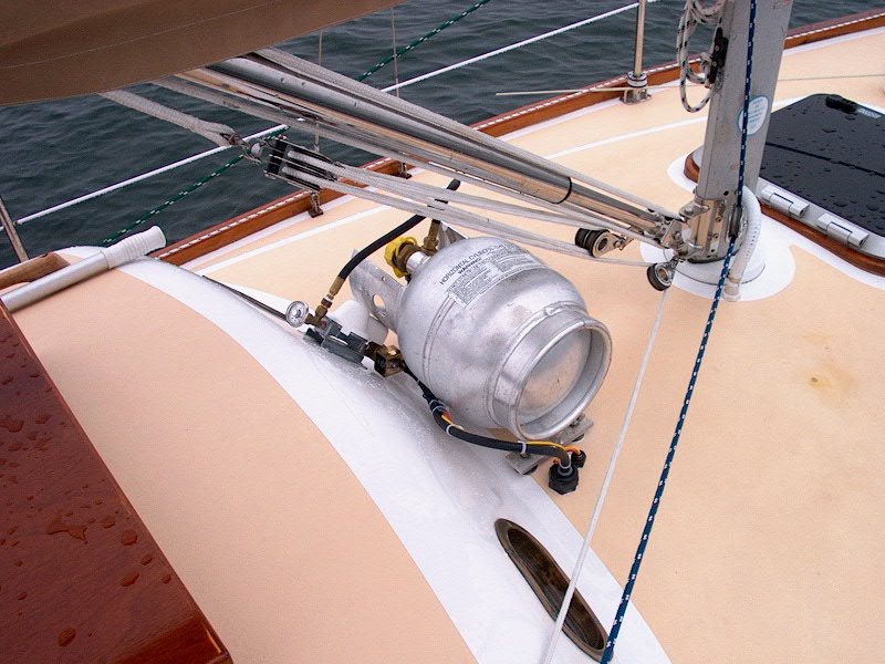
Holding this idea in reserve, I looked into
other options. After much discussion, eventually we decided to install the
tank--without a box--on the coachroof aft of the mast. While the tank and
regulator will be exposed here, it seemed the best all-round location.
We'll build a canvas cover for the whole thing to clean it up a little and help
protect it from the weather and other damage. I don't know what I'm going
to do with my nice deck box.
 To
make the tank easily removable for filling, I installed four bolts from inside
the cabin (in the head); these are long enough to penetrate the cabin, allow for
room for a nut and washer (to hold the bolts permanently in place), and allow
for the tank to sit over the exposed ends for securing with wing nuts for easy
removal. I gobbed lots of caulk around the boltholes and beneath the
fender washers. To
make the tank easily removable for filling, I installed four bolts from inside
the cabin (in the head); these are long enough to penetrate the cabin, allow for
room for a nut and washer (to hold the bolts permanently in place), and allow
for the tank to sit over the exposed ends for securing with wing nuts for easy
removal. I gobbed lots of caulk around the boltholes and beneath the
fender washers.
|
|
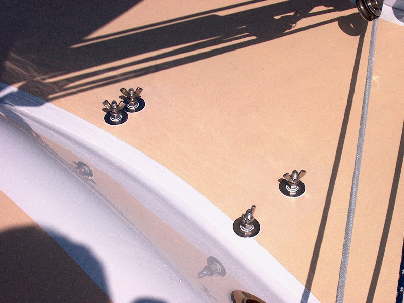
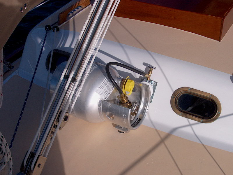
 The
tank rests neatly on these four bolts, and is secured with wing nuts and lock
washers. It's open to the atmosphere, so venting won't be a concern.
It clears the boom vang nicely, and is pretty much out of the way here. The
tank rests neatly on these four bolts, and is secured with wing nuts and lock
washers. It's open to the atmosphere, so venting won't be a concern.
It clears the boom vang nicely, and is pretty much out of the way here.
|
|
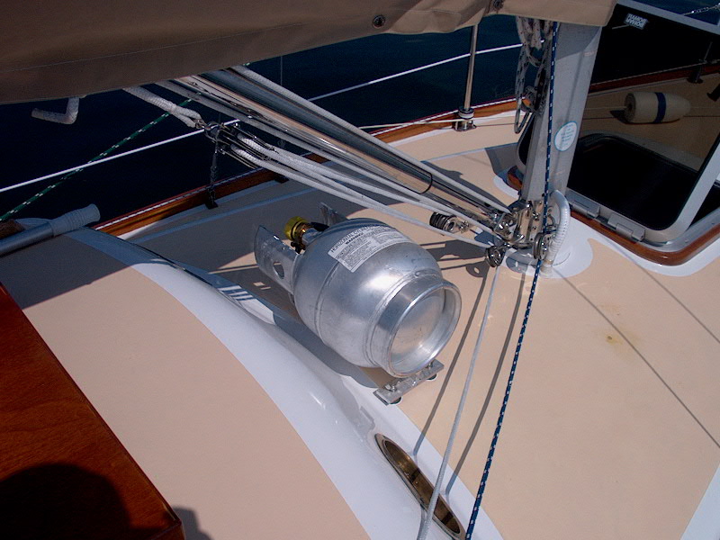
 I
installed a remote regulator assembly, attached to the tank with a pigtail, on
the forward end of the cabin trunk bump. It's sort of tucked in behind the
"top" end of the tank, the end with the valve assembly, which helps
protect it from the weather. To the regulator, I attached, using a series
of brass nipples, an electric solenoid control, which is switched on and off by
a panel in the cabin. This valve keeps the system closed off when not in I
installed a remote regulator assembly, attached to the tank with a pigtail, on
the forward end of the cabin trunk bump. It's sort of tucked in behind the
"top" end of the tank, the end with the valve assembly, which helps
protect it from the weather. To the regulator, I attached, using a series
of brass nipples, an electric solenoid control, which is switched on and off by
a panel in the cabin. This valve keeps the system closed off when not in  use;
I will soon be installing a vapor alarm for the bilge, which, in addition to an
audible alarm, will shut the use;
I will soon be installing a vapor alarm for the bilge, which, in addition to an
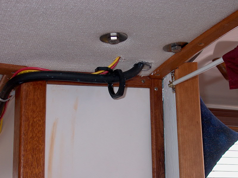
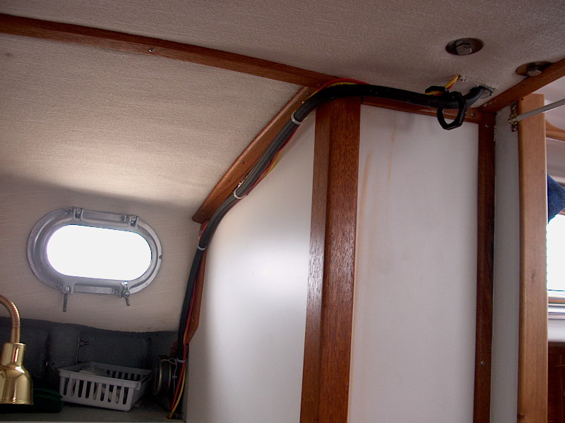
audible alarm, will shut the    solenoid if vapors are detected. Downstream
of the solenoid, the 15' hose run is secured, which runs through a vapor-tight
cable fitting into the head, then across the bulkhead, where it disappears
behind the main cabin settee backs for its run aft to the stove. I
installed a plastic cover over the regulator to protect it and the integral vent
from water. The solenoid wires run through another vapor-tight fitting near the
hose exit, and are tied up alongside. I need to build a wooden trim piece
to hide the hose and wiring inside the boat--this will probably happen during
the off season. (I copped out--see my trim solution here.) solenoid if vapors are detected. Downstream
of the solenoid, the 15' hose run is secured, which runs through a vapor-tight
cable fitting into the head, then across the bulkhead, where it disappears
behind the main cabin settee backs for its run aft to the stove. I
installed a plastic cover over the regulator to protect it and the integral vent
from water. The solenoid wires run through another vapor-tight fitting near the
hose exit, and are tied up alongside. I need to build a wooden trim piece
to hide the hose and wiring inside the boat--this will probably happen during
the off season. (I copped out--see my trim solution here.)
|
|
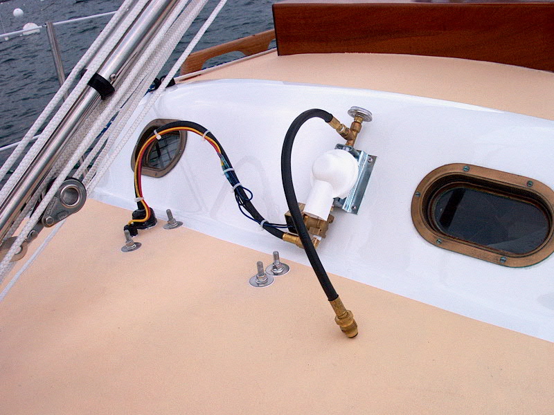
 Finally,
I completed the wiring connections at the tank (solenoid) end and behind the
Trident panel according to the instructions included with the panel. Finally,
I completed the wiring connections at the tank (solenoid) end and behind the
Trident panel according to the instructions included with the panel.
|
|
  The regulator assembly is admittedly not the
most attractive thing in the world, but, with the tank installed, is fairly
hidden--we plan a canvas cover for everything soon anyway. Sometimes,
function has to come before form (not often, though...). The regulator assembly is admittedly not the
most attractive thing in the world, but, with the tank installed, is fairly
hidden--we plan a canvas cover for everything soon anyway. Sometimes,
function has to come before form (not often, though...).
Before starting the system for the first time,
I performed several leak tests. First, I opened the tank valve until the
pressure gauge on the regulator rose to 110 (a normal reading for 70
degrees). Then, I shut the valve and waited a number of minutes before
checking the gauge again. It didn't move; if there had been a leak
somewhere in the line, or at a fitting, the pressure would have gone down.
Then, I brushed some very soapy water on every joint and nipple, looking for
bubbles that would indicate leakage. None. With these critical
safety tests complete, I was able to test-light the stove; in its initial test,
the stove and oven worked great! We used it for an entire--if
brief--season with excellent results. I didn't get around to installing
the vapor-detector kit right away.
Update 19
March 2002
Finally, I got around to
installing the sniffer/alarm system after the first season. It was one of
those small projects that I just could never find the time for during the
summer.
Installation was fairly
straightforward. The kit includes a sensor assembly, which is to be
mounted somewhere fumes might collect if there were a leak, and an additional
circuit board and reset button that is intended for installation on the original
Trident gas control panel. These panels are sold complete with the alarm
setup already installed, or separately--as I had purchased them. I did
this because the store didn't have the complete system in stock when I needed
it, so I bought the normal panel at that time, and ordered the upgrade alarm kit
later on.
|
|
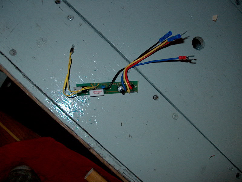
 This
is the new circuit board. It features whatever electronic wizardry that
makes it work, along with four new wires, and an alarm light circuit (left, with
the yellow wires) and a reset button--the black knob next to the bundle of four
wires. I followed the included instructions and installed it on the back
of the Trident panel. First, I had to enlarge the cutout in my
switch panel board to allow it to fit properly. Access is tight, so
I used a serrated narrow-blade knife that I had on board to saw out the
opening. It worked surprisingly well, but I didn't get a perfect cut--not
that it matters, since the opening is hidden anyway. This
is the new circuit board. It features whatever electronic wizardry that
makes it work, along with four new wires, and an alarm light circuit (left, with
the yellow wires) and a reset button--the black knob next to the bundle of four
wires. I followed the included instructions and installed it on the back
of the Trident panel. First, I had to enlarge the cutout in my
switch panel board to allow it to fit properly. Access is tight, so
I used a serrated narrow-blade knife that I had on board to saw out the
opening. It worked surprisingly well, but I didn't get a perfect cut--not
that it matters, since the opening is hidden anyway.
|
|
 Then, I removed two
blanks that filled the holes for the new reset button and red alarm light, and
installed the circuit board over two studs that I screwed into threaded holes
provided in the back of the panel. The studs hold the circuit board in the
proper place. I installed a red plastic lens for the alarm light, and
pressed the wired bulb into the lens from the back. Then, I attached two
of the included wires to the original circuit breaker switch, as directed by the
instructions. The other two wires will be connected a little later on,
after I install the vapor sensor. Then, I removed two
blanks that filled the holes for the new reset button and red alarm light, and
installed the circuit board over two studs that I screwed into threaded holes
provided in the back of the panel. The studs hold the circuit board in the
proper place. I installed a red plastic lens for the alarm light, and
pressed the wired bulb into the lens from the back. Then, I attached two
of the included wires to the original circuit breaker switch, as directed by the
instructions. The other two wires will be connected a little later on,
after I install the vapor sensor.
|
|
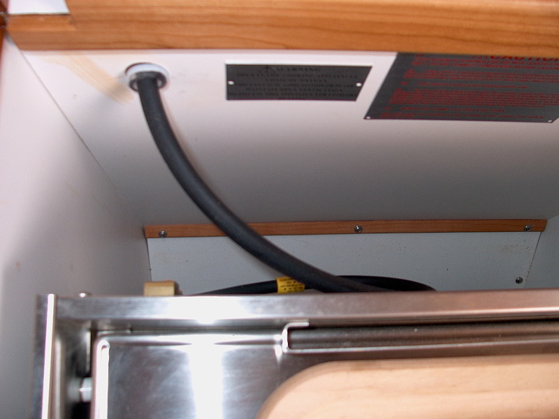
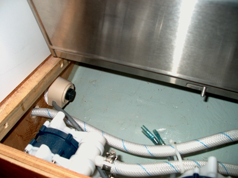
 I
installed the vapor sensor in a compartment beneath the stove. I was a
little unsure where to put this. My first instinct was the bilge, but
looking at the sensor I decided that it looked entirely UN-waterproof, and the
chances of it getting at least damp are pretty high were it to be located in the
bilge. I settled for the space directly beneath the stove, where the water
pumps are installed. It seems logical that propane might collect here if
there were a leak around the stove. I attached it with a blob of
caulk, and duct-taped it in place while the caulk cured. I
installed the vapor sensor in a compartment beneath the stove. I was a
little unsure where to put this. My first instinct was the bilge, but
looking at the sensor I decided that it looked entirely UN-waterproof, and the
chances of it getting at least damp are pretty high were it to be located in the
bilge. I settled for the space directly beneath the stove, where the water
pumps are installed. It seems logical that propane might collect here if
there were a leak around the stove. I attached it with a blob of
caulk, and duct-taped it in place while the caulk cured.
|
|
 The
sensor is connected to a power source and to other wires on the Trident control
panel with a length of triplex wire. I ran the wire behind the engine room
and through my wire chases to the electrical panel, and connected the various
wires as directed by the instructions. One wire runs to the positive
distribution buss; another, along with one of the wires on the new circuit
board, grounds to the negative distribution buss; and the third connects to the
final wire on the circuit board (exact function unknown...but that's where it
goes!). You can see these wires secured to one of the thick red
battery cables in the photo towards the right center. The negative buss is
at the top of the photo; the positive buss is just below, with the red wires
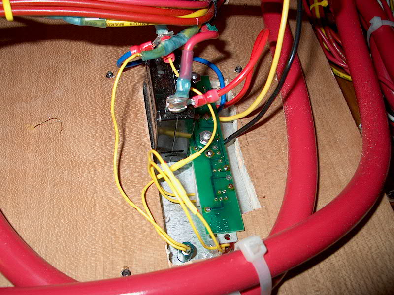
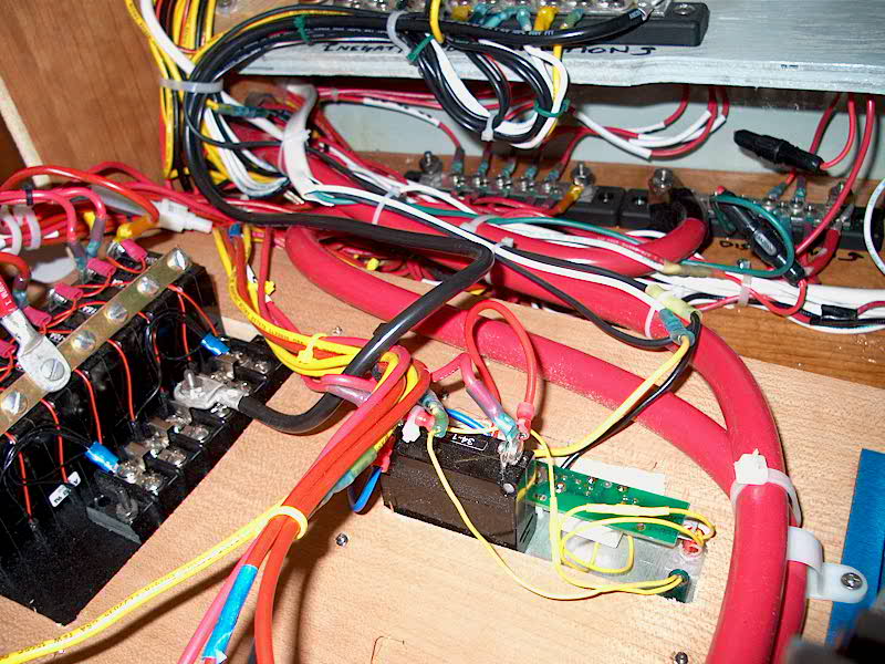
attached. The
sensor is connected to a power source and to other wires on the Trident control
panel with a length of triplex wire. I ran the wire behind the engine room
and through my wire chases to the electrical panel, and connected the various
wires as directed by the instructions. One wire runs to the positive
distribution buss; another, along with one of the wires on the new circuit
board, grounds to the negative distribution buss; and the third connects to the
final wire on the circuit board (exact function unknown...but that's where it
goes!). You can see these wires secured to one of the thick red
battery cables in the photo towards the right center. The negative buss is
at the top of the photo; the positive buss is just below, with the red wires
attached.
|
UPDATE
The alarm
system worked fine when first connected, but at one point during our cruise it
started going off intermittently, then almost continuously, so eventually I had
to disconnect the buzzer. Troubleshooting and repair of this is on the
project list for winter 2002. As usual, these silly electronic devices are
more trouble than they're worth. In 2008, I removed the sniffer and its
wiring completely. |
|

 With
With