|
Fuel System
This page was last updated on 10
November 2001.
|
|
 After
installing the fuel tank, I began making up the
final hose connections and installing other equipment, including a new fuel
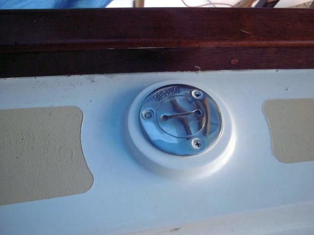
filter. The first step in this process was to install a new diesel deck
plate on the starboard coaming. Using polysulfide caulk beneath, I screwed
the fitting into place. Next, I clamped a new length of 1 1/2" Type
A2 fuel fill hose to the nipple with two AWAB hose clamps. I snaked the
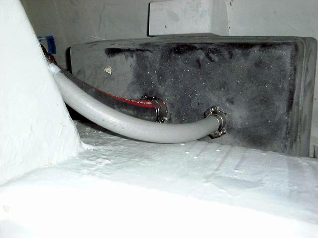
hose behind the cockpit After
installing the fuel tank, I began making up the
final hose connections and installing other equipment, including a new fuel
filter. The first step in this process was to install a new diesel deck
plate on the starboard coaming. Using polysulfide caulk beneath, I screwed
the fitting into place. Next, I clamped a new length of 1 1/2" Type
A2 fuel fill hose to the nipple with two AWAB hose clamps. I snaked the
hose behind the cockpit  locker and secured it in place with nylon tie wraps,
and, after cutting it to length, secured the other end to the fuel tank with two
more clamps. locker and secured it in place with nylon tie wraps,
and, after cutting it to length, secured the other end to the fuel tank with two
more clamps.
|
|
 I ran the 5/8" ID vent line
from the tank outlet up behind the cockpit seat and aft along the starboard side
to a new
screened vent fitting I installed in the transom. I secured the new vent
fitting with polysulfide beneath the outside and a bronze 90º threaded fitting
on the inside, to which I attached a 5/8" bronze nipple. The hose was
secured to the nipple with double hose clamps. I really enjoyed the head rush
I got as I hung upside down inside the lazarette trying to secure the clamps
and, especially, while I secured the plastic brackets to support the hose along
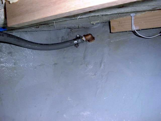
its run. I ran the 5/8" ID vent line
from the tank outlet up behind the cockpit seat and aft along the starboard side
to a new
screened vent fitting I installed in the transom. I secured the new vent
fitting with polysulfide beneath the outside and a bronze 90º threaded fitting
on the inside, to which I attached a 5/8" bronze nipple. The hose was
secured to the nipple with double hose clamps. I really enjoyed the head rush
I got as I hung upside down inside the lazarette trying to secure the clamps
and, especially, while I secured the plastic brackets to support the hose along
its run.
|
 I
began the fuel supply installation by installing a Racor 215 fuel/water
separator on the starboard side of the engine room, mounted up high and easily
accessible for service. I bolted this through the bulkhead from the
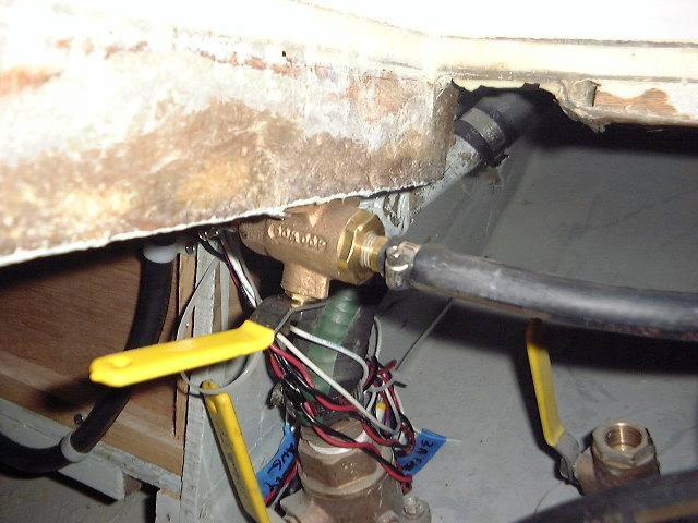
outside (in the galley). Next, I installed a bronze shutoff inside the
cockpit sole access hatch near the fuel tank, after screwing in two bronze
nipples for the hose. Then, I ran a length of Type A1 hose from the tank
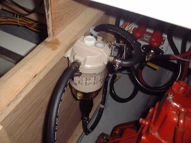
outlet to I
began the fuel supply installation by installing a Racor 215 fuel/water
separator on the starboard side of the engine room, mounted up high and easily
accessible for service. I bolted this through the bulkhead from the
outside (in the galley). Next, I installed a bronze shutoff inside the
cockpit sole access hatch near the fuel tank, after screwing in two bronze
nipples for the hose. Then, I ran a length of Type A1 hose from the tank
outlet to  the
shutoff, and another from the shutoff towards the filter, securing the hose with
plastic clamps along the way. I left this piece short and installed an
outboard motor-type squeeze bulb in the line on the suction side of the filter;
the idea is that this will help reprime the system when I have to bleed the
injector at some point in the future (a virtually guaranteed occurrence).
Then, I connected the bulb to the filter inlet, and the filter outlet to the
secondary filter located on the engine. the
shutoff, and another from the shutoff towards the filter, securing the hose with
plastic clamps along the way. I left this piece short and installed an
outboard motor-type squeeze bulb in the line on the suction side of the filter;
the idea is that this will help reprime the system when I have to bleed the
injector at some point in the future (a virtually guaranteed occurrence).
Then, I connected the bulb to the filter inlet, and the filter outlet to the
secondary filter located on the engine. |
|
The fuel return line runs from
the injector back to the secondary filter, rather than back to the tank as I had
originally expected. This is a standard arrangement on the SB12, and I
can't see a reason to change it. I will blank off the return fitting on
the tank, since it won't be needed.
Update!!
When I installed
the new diesel engine (Yanmar 2GM20F), it had a more conventional return fuel
arrangement, so I reinstalled the return fitting on the tank and ran a hose
there. Details can be found on the new engine installation pages. Click here
to go directly to the proper page.
|
|