|
Exhaust
and Cooling Systems
This page was last updated on 10
November 2001
|
|
Engine
Cooling System
 The
Yanmar is raw water-cooled, so the cooling system is quite
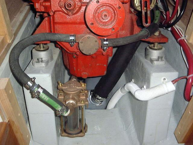
straightforward. As an upgrade to the standard system, I installed a Perko
bronze sea strainer in the engine room, mounted in a convenient location on the
inside of the starboard engine mount for easy inspection and servicing. I
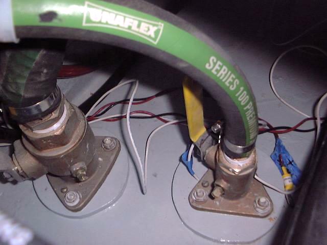
used 90º bronze hose nipples to The
Yanmar is raw water-cooled, so the cooling system is quite
straightforward. As an upgrade to the standard system, I installed a Perko
bronze sea strainer in the engine room, mounted in a convenient location on the
inside of the starboard engine mount for easy inspection and servicing. I
used 90º bronze hose nipples to  make hose connection a little easier. The
inlet is aft, towards the engine, and points straight down, which makes for an
easy connection with the 3/4" hose that runs from the seacock aft of the
engine room. From the strainer output, a short length of 3/4" hose
runs into a reducing nipple (plastic--I can't find a bronze one), where it
changes to 1/2" hose--the size required for the connections on the
engine. Then, it's on to the raw water pump front and center on the
engine. From there, another length of hose runs aft to the internal engine
chambers for eventual discharge and injection into the exhaust mixer. I
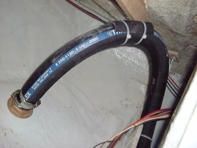
have replaced all original cooling system hoses with new 1/2" hardwall
wire-reinforced wet exhaust hose. make hose connection a little easier. The
inlet is aft, towards the engine, and points straight down, which makes for an
easy connection with the 3/4" hose that runs from the seacock aft of the
engine room. From the strainer output, a short length of 3/4" hose
runs into a reducing nipple (plastic--I can't find a bronze one), where it
changes to 1/2" hose--the size required for the connections on the
engine. Then, it's on to the raw water pump front and center on the
engine. From there, another length of hose runs aft to the internal engine
chambers for eventual discharge and injection into the exhaust mixer. I
have replaced all original cooling system hoses with new 1/2" hardwall
wire-reinforced wet exhaust hose.
|
|
 UPDATE!!
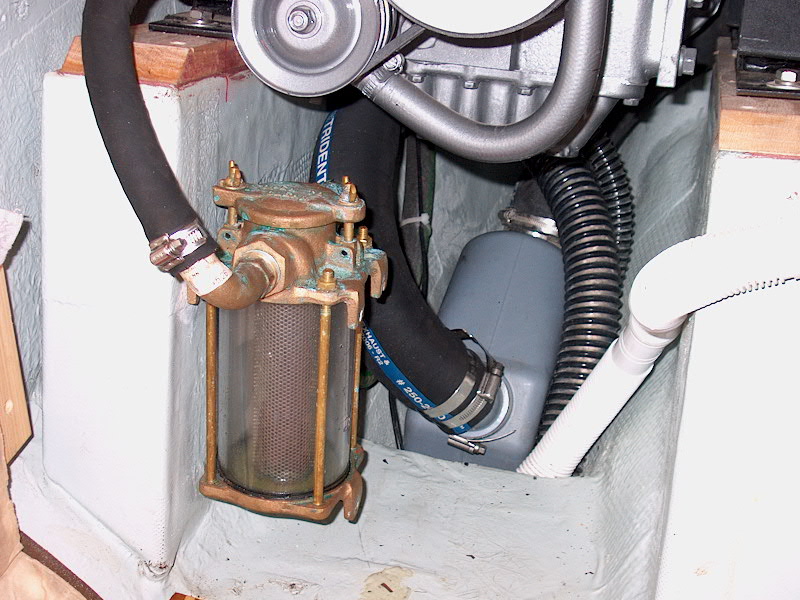
I really didn't have to make any significant
changes to the raw water intake system when I installed the new Yanmar
2GM20F. The only thing I changed was the hose leading from the sea
strainer to the raw water pump--the new fitting on the engine is a larger size,
so I was able to eliminate the reducing nipple that I had in place before.
All the better! UPDATE!!
I really didn't have to make any significant
changes to the raw water intake system when I installed the new Yanmar
2GM20F. The only thing I changed was the hose leading from the sea
strainer to the raw water pump--the new fitting on the engine is a larger size,
so I was able to eliminate the reducing nipple that I had in place before.
All the better!
|
|
Exhaust
System
Before lifting the
engine into the boat, I had removed the exhaust mixer and thermostat
housing. For some reason, I never reinstalled it, so the first step to
complete the exhaust system was to reinstall this part with new gaskets.
Next, I ran a length of 2" ID hardwall wire-reinforced exhaust hose
(2" is the size of the outlet on the exhaust mixer) from inside the cabin
through the port side of the engine room and up to the mixer, where I installed
it with two hose clamps. I did it this way so that I could attach the
bitter end, but still have the full length of hose beneath the engine for proper
fitting to the new Vetus Waterlock muffler. The hose is expensive, and I
didn't want to make a mistake cutting it. The hose runs between the fore
and aft engine mounts and then downwards towards the bilge.
With the full length
of hose in place, I determined the proper length for the first section (exhaust
mixer to Waterlock) and cut it to length with a serrated knife and wire cutters
to nip the helical wire inside the hose. The Waterlock fits very nicely in
the bilge beneath the engine--it's almost like it's tailor made for the
space. I decided on the Waterlock for this very reason, having heard of
other Triton owners who have had success with the same equipment. The
input fitting on the Waterlock is removable, and I found it easier to remove the
swivel fitting and clamp the hose to it first, then to reinsert the swivel
fitting into the chamber. For now, though, I left it off.
|
|
 Next,
I took the remaining length of hose and, from the cabin, ran it beneath the
engine and up the port side forward of the cockpit scupper seacock. This
took a lot of huffing and puffing, as the hose is quite stiff and tough to
bend. The idea is to keep the hose out of the way of the propeller shaft
and couplings, and running it in this manner will do just that. Later,
I'll install some sort of clamps to keep things in place. When I had most
of the hose pushed through, I connected the bitter end to the output of the
Waterlock with two clamps (AWAB) and placed the muffler in the proper position
beneath the engine. With this done, I was able to remove the slack from
the output hose and reinsert the input fitting and clamp it down. The
muffler is quite rigidly held in place with the hoses and Next,
I took the remaining length of hose and, from the cabin, ran it beneath the
engine and up the port side forward of the cockpit scupper seacock. This
took a lot of huffing and puffing, as the hose is quite stiff and tough to
bend. The idea is to keep the hose out of the way of the propeller shaft
and couplings, and running it in this manner will do just that. Later,
I'll install some sort of clamps to keep things in place. When I had most
of the hose pushed through, I connected the bitter end to the output of the
Waterlock with two clamps (AWAB) and placed the muffler in the proper position
beneath the engine. With this done, I was able to remove the slack from
the output hose and reinsert the input fitting and clamp it down. The
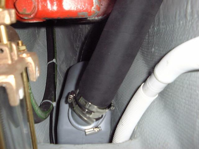
muffler is quite rigidly held in place with the hoses and  the
narrow confines of the bilge, but I will probably find some more permanent means
of securing it. The thumbnail (right) shows how the Waterlock looks from
the front, inside the cabin. the
narrow confines of the bilge, but I will probably find some more permanent means
of securing it. The thumbnail (right) shows how the Waterlock looks from
the front, inside the cabin.
|
|
 The
next issue deals with reducing the size of the exhaust hose from 2" to
1-1/2". This is necessary because the new through hull fitting I
installed in the counter is for 1-1/2" hose, and I didn't want to change
it. Reducing the hose size is a The
next issue deals with reducing the size of the exhaust hose from 2" to
1-1/2". This is necessary because the new through hull fitting I
installed in the counter is for 1-1/2" hose, and I didn't want to change
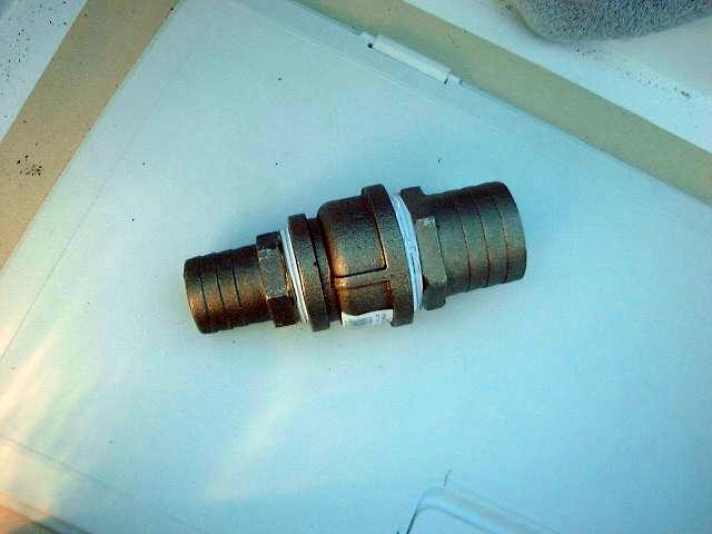
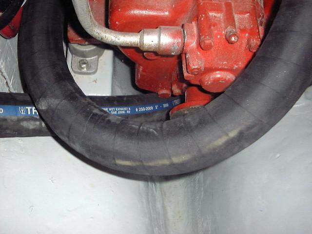
it. Reducing the hose size is a  seemingly
simple matter--except that no one makes the proper reducers. I first
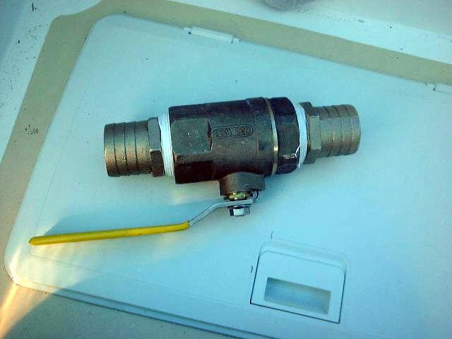
looked for a fitting to work with my bronze exhaust shutoff valve (photo top
left), which is for 2" hose. I hoped to find a 2" pipe thread
fitting with a 1-1/2" hose nipple on it--but none exists. Next, I
looked for a hose-to-hose reducer, from 2" to 1-1/2"; they make
similar fittings out of plastic that you can find in hardware stores
everywhere. Of course, I didn't want plastic, and I couldn't find a bronze
fitting like this for the seemingly
simple matter--except that no one makes the proper reducers. I first
looked for a fitting to work with my bronze exhaust shutoff valve (photo top
left), which is for 2" hose. I hoped to find a 2" pipe thread
fitting with a 1-1/2" hose nipple on it--but none exists. Next, I
looked for a hose-to-hose reducer, from 2" to 1-1/2"; they make
similar fittings out of plastic that you can find in hardware stores
everywhere. Of course, I didn't want plastic, and I couldn't find a bronze
fitting like this for the  life
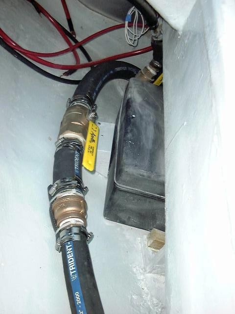
of me. The strange thing is, they make these fittings that go up in size,
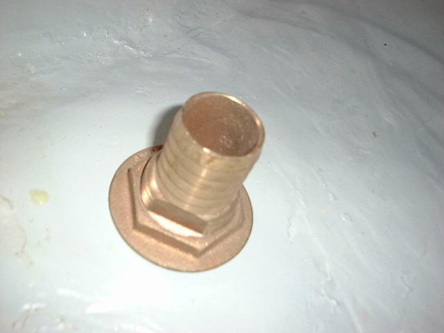
but not down--or at least not with the sizes I needed. I finally stumbled
upon a double female union fitting that reduced from 2" to 1-1/2";
then, it was just a matter of inserting the proper hose nipples in each side.
(photo bottom left) Phew--I thought I'd have to replace the through
hull. life
of me. The strange thing is, they make these fittings that go up in size,
but not down--or at least not with the sizes I needed. I finally stumbled
upon a double female union fitting that reduced from 2" to 1-1/2";
then, it was just a matter of inserting the proper hose nipples in each side.
(photo bottom left) Phew--I thought I'd have to replace the through
hull.
|
|
 The
next thing to do was to cut the 2" hose to the proper length. I
decided to install the shutoff adjacent to one of the wooden fuel tank supports,
which is easily accessible through the port cockpit locker and also provides a
convenient place to secure the heavy bronze fitting. After cutting the
hose, I installed it on the shutoff valve, and secured the valve to the block
with a couple nylon cable ties. To cushion the valve where it rests on the
hull, I cut a piece of rubber hose and slit it down the middle, and secured this
beneath the valve with more cable ties. Then, on the discharge side, I The
next thing to do was to cut the 2" hose to the proper length. I
decided to install the shutoff adjacent to one of the wooden fuel tank supports,
which is easily accessible through the port cockpit locker and also provides a
convenient place to secure the heavy bronze fitting. After cutting the
hose, I installed it on the shutoff valve, and secured the valve to the block
with a couple nylon cable ties. To cushion the valve where it rests on the
hull, I cut a piece of rubber hose and slit it down the middle, and secured this
beneath the valve with more cable ties. Then, on the discharge side, I  added
a short length of 2" hose, then installed the made-up reducing fitting,
also cushioned with some slit rubber hose. All hose connections are
secured with double AWAB clamps. Then, I installed a final length of
1-1/2" exhaust hose that runs into the lazarette, into a loop beneath the
deck, and down to the through hull fitting in the counter. The loop is
designed to help prevent backflow if the outlet becomes submerged; the shutoff
valve is a little added insurance against the same, for use especially if
running before a heavy sea. added
a short length of 2" hose, then installed the made-up reducing fitting,
also cushioned with some slit rubber hose. All hose connections are
secured with double AWAB clamps. Then, I installed a final length of
1-1/2" exhaust hose that runs into the lazarette, into a loop beneath the
deck, and down to the through hull fitting in the counter. The loop is
designed to help prevent backflow if the outlet becomes submerged; the shutoff
valve is a little added insurance against the same, for use especially if
running before a heavy sea.
The exhaust system
is complete!eath the engine, so the hose
could take a more direct route without needing to twist between the engine
mounts. I was able to cut off nearly two feet of hose as a result.
|
|