|
Bilge Pumps
This page was last updated on 10 November 2001.
|
|
I installed two bilge pumps on board: a large
Henderson MK IV manual diaphragm pump (the same one used by the Lavac toilet) and an electric Rule 2000 GPH with automatic
switch.
 I
began the installation for the automatic pump by installing a three-way switch
in the systems panel. Then, I ran three wires from behind the panel down
and through the engine room to the bilge in the main salon, protecting the wires
where they run through the engine room by running them through a length of old
plastic hose that I had around. I secured the hose to the engine mounts to
keep it in place. The three wires are for the ground, power supply (+) and
automatic switch. A little later, I will make the connections at the pump
according to the supplied wiring diagram. I
began the installation for the automatic pump by installing a three-way switch
in the systems panel. Then, I ran three wires from behind the panel down
and through the engine room to the bilge in the main salon, protecting the wires
where they run through the engine room by running them through a length of old
plastic hose that I had around. I secured the hose to the engine mounts to
keep it in place. The three wires are for the ground, power supply (+) and
automatic switch. A little later, I will make the connections at the pump
according to the supplied wiring diagram.
|
|
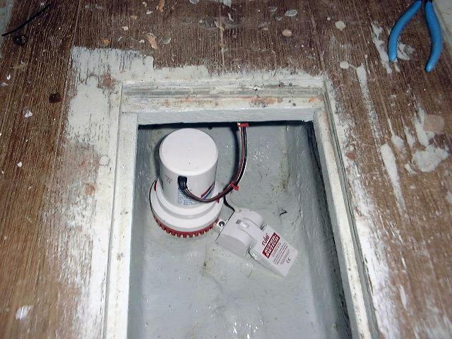 Next, I chose the position for the pump in the bilge.
#381 has the shallow bilge, so access is easy to all portions. The lowest
point of the bilge is directly beneath the cabin sole between the two access
hatches, so I positioned the pump base and secured it with two screws, sealing
the holes with polysulfide. There's plenty of boat and fiberglass beneath the
bottom of the bilge so I didn't worry about installing two small screws directly
into the glass. The switch secures
to a bracket that snaps into the pump base, a convenient installation that required
no additional screws into the hull. I made sure that the switch had room
to move up and down freely. Next, I chose the position for the pump in the bilge.
#381 has the shallow bilge, so access is easy to all portions. The lowest
point of the bilge is directly beneath the cabin sole between the two access
hatches, so I positioned the pump base and secured it with two screws, sealing
the holes with polysulfide. There's plenty of boat and fiberglass beneath the
bottom of the bilge so I didn't worry about installing two small screws directly
into the glass. The switch secures
to a bracket that snaps into the pump base, a convenient installation that required
no additional screws into the hull. I made sure that the switch had room
to move up and down freely.
With the pump installed, I made the final wiring connections
according to the supplied wiring diagrams. There are three wires--a ground
(black), the power supply (brown), and a third wire (brown) which leads to the
panel light. I made the connections with waterproof butt connectors, which
contain an adhesive that, when heated, melts around the connection, forming a
secure, watertight seal inside the connector's heat shrink tubing. They
cost more, but are worth it. I secured the wires and the protective hose
(see above) to the underside of the cabin sole, far out along the hull behind
the wooden supports for the bilge access hatches.
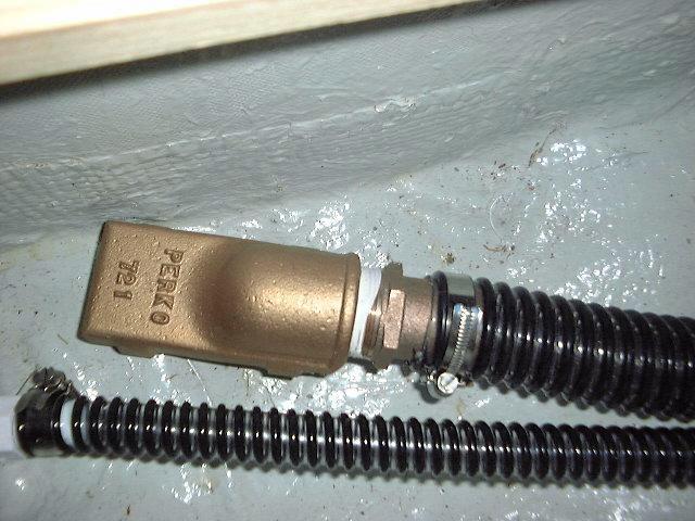
I ran the 3/4" discharge hose through the
engine room, beneath the fuel tank, and aft to a through hull fitting in the
counter. I fitted a check valve in the line just downstream of the pump to
keep the water in the hose from running back into the bilge when the pump shuts
off; it's a rather long, uphill hose run, and this amount of water could
possibly cause the pump to cycle repeatedly, so I'll take the somewhat reduced
discharge rate and use the check valve.
|
|
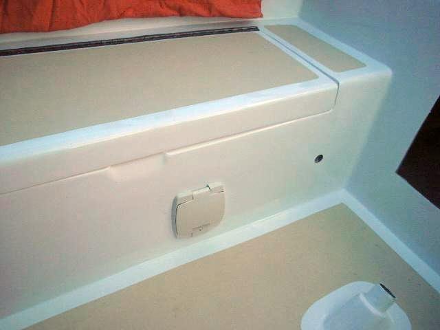
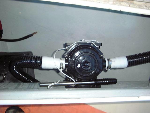 I
mounted the Henderson manual pump in the starboard cockpit locker.
Mounting the pump required cutting a large (about 3-4" diameter) hole in
the side of the cockpit well, which is always fun. Then, it was a
relatively simple matter of screwing the outside place through the cockpit well
and into the back of the pump, which was I
mounted the Henderson manual pump in the starboard cockpit locker.
Mounting the pump required cutting a large (about 3-4" diameter) hole in
the side of the cockpit well, which is always fun. Then, it was a
relatively simple matter of screwing the outside place through the cockpit well
and into the back of the pump, which was  fitted
with a supplied conversion ring. I ran 1-1/2" corrugated hose from a
low point in the bilge (just aft of the electric pump), beneath the engine and
fuel tank (keeping the hose well clear of the prop shaft, of course) and up to
the pump housing. The discharge line then runs aft to a fitted
with a supplied conversion ring. I ran 1-1/2" corrugated hose from a
low point in the bilge (just aft of the electric pump), beneath the engine and
fuel tank (keeping the hose well clear of the prop shaft, of course) and up to
the pump housing. The discharge line then runs aft to a  through hull in
the counter. At the suction end, I installed a heavy bronze strainer that
holds the hose in place and will prevent any debris from getting sucked into the
hose or pump. through hull in
the counter. At the suction end, I installed a heavy bronze strainer that
holds the hose in place and will prevent any debris from getting sucked into the
hose or pump.
|
|
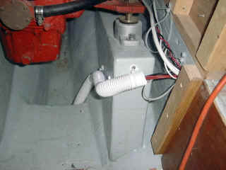
To keep the number of through hulls to a
minimum, I decided to conjoin the two discharges just above the through hull in
the counter. This required a fairly complex set of fittings, since the
hoses are different sizes. First, I cut the 1-1/2" line and 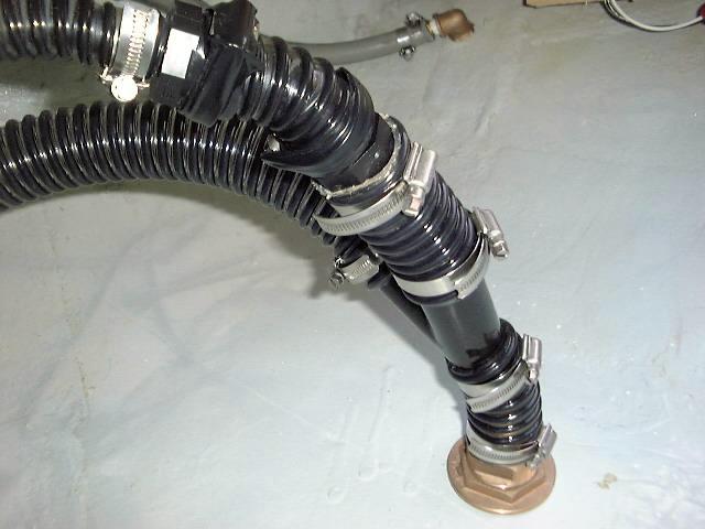 inserted
a 1-1/2" plastic "Y" fitting in place. Then, I connected
the other cut end of the line to one side of the "Y". The
3/4" discharge line from the manual pump required some more work,
however. First, I had to ramp the 3/4" up to a 1-1/8" size
through one plastic fitting, then I increased it from 1-1/8" up to
1-1/2" in another fitting just downstream, before connecting that (through
a short length of hose) to the other side of the "Y" fitting. I
should have chosen 1-1/8" hose for the manual pump--it's actual discharge
size--but I had thought it was 3/4" when I bought the hose and check valve,
and they don't make a larger check valve anyway. This is Rube
Goldberg-esque in its silly complexity, but is constructed and should serve
just fine. Tile will tell, and eventually I'll probably have a better
solution at hand. inserted
a 1-1/2" plastic "Y" fitting in place. Then, I connected
the other cut end of the line to one side of the "Y". The
3/4" discharge line from the manual pump required some more work,
however. First, I had to ramp the 3/4" up to a 1-1/8" size
through one plastic fitting, then I increased it from 1-1/8" up to
1-1/2" in another fitting just downstream, before connecting that (through
a short length of hose) to the other side of the "Y" fitting. I
should have chosen 1-1/8" hose for the manual pump--it's actual discharge
size--but I had thought it was 3/4" when I bought the hose and check valve,
and they don't make a larger check valve anyway. This is Rube
Goldberg-esque in its silly complexity, but is constructed and should serve
just fine. Tile will tell, and eventually I'll probably have a better
solution at hand.
The bilge pumps are complete and ready for
action...although I don't expect any water in the bilges!
UPDATE! After a
season, I have been very happy with the performance of the bilge pumps.
Frankly, I never once used the manual pump, and the automatic pump did its job
with no trouble at all. I keep the bilges very clean, so that helps
prevent clogging of the pumps with debris--or, more commonly, clogging the
automatic switch. I never had a problem with this during the first season.
After winter storage the first year, the check valve I installed in the
automatic pump discharge failed, so I removed it completely. Those things
simply never work out, but I suppose it was worth a try.
Further updates will be posted
as applicable. |
|