|
Replacing the Cockpit Scuppers (Page 2)
This page was last updated on 14 January 2004.
| Page 1 | |
Installing the New Scupper Castings
The next morning, I began by marking the center point where I wanted the new scuppers to end up; I did this by holding the
casting upside down in place, and marking through the cast center hole with a pencil. Then, I drilled a pilot hole so
that the pilot bit on the hole saw would have a place to start, reducing the tendency for it to walk.
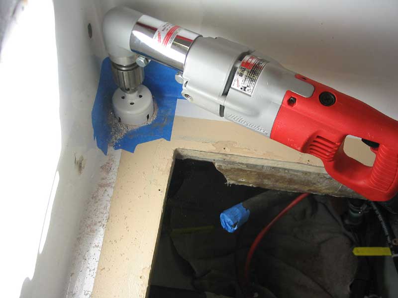
Then, I cut the two 2-1/2" holes with a hole saw chucked into my big electrician's right angle drill, which I purchased
during the barn construction. The cutting was easy, and controlling the drill was no trouble. In only a few
moments, both holes were drilled, and I was ready to proceed.
|
|

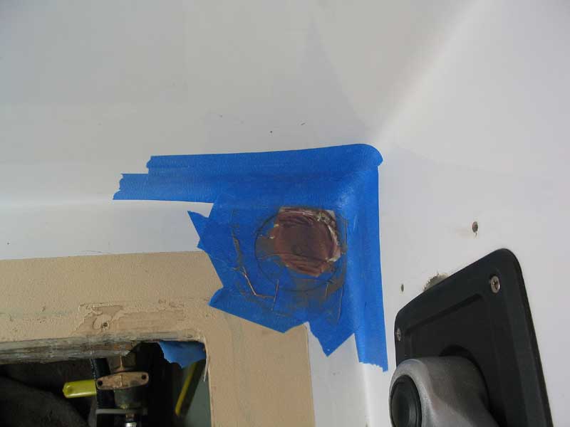
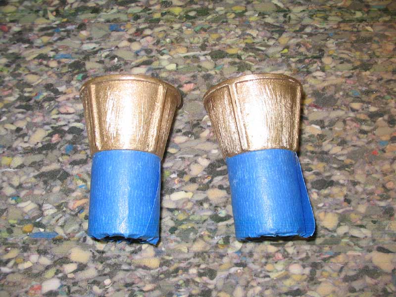
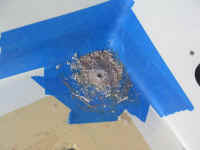
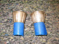
I marked the outline of the scupper and the center for the pilot bit.
|
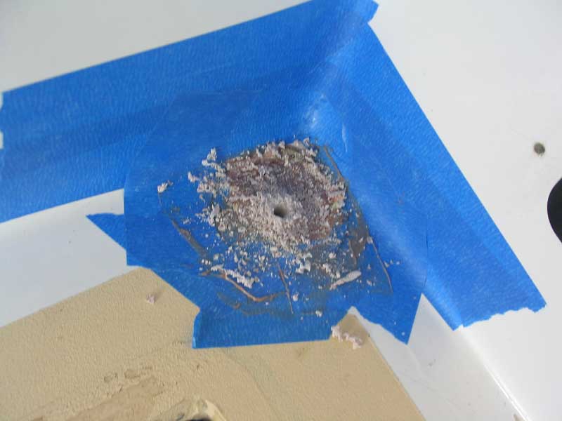
Then I drilled a pilot hole.
|
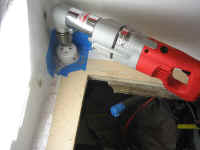
I cut the large holes with a 2-1/2" hole saw in my big right angle drill.
|

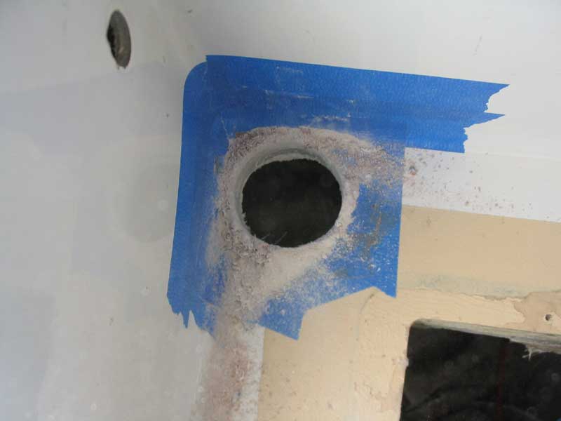
The completed scupper hole.
|
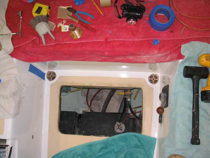
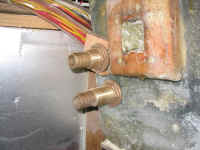
After test-fitting the scuppers, I could see that I needed to slightly enlarge the opening at
the top, so the topmost portion of the casting would fit into the hole. I wanted a tight friction fit, so I used a
small drum sander in my cordless drill to widen the holes enough. Then, I used a small grinder to carefully sand the
underside of the cockpit in way of the holes, to get some semblance of a flat surface for my next step in the process. |
|

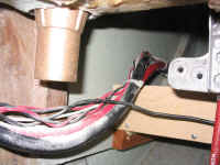
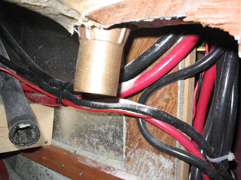
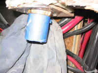
Port and Starboard fittings, respectively, from below during the initial test fit.
The wires look loose because I unsecured them early in the process to avoid damage;
they'll be resecured later.
|
During the restoration of the boat, I reinforced the cockpit sole by adding 1/2" balsa core
on top of the original surface, and then glassing over the top of the new core. That I had done this was fortuitous at
this juncture, as it gave me a total cockpit sole thickness of about 3/4"--far more than it would have been if I still
had original construction. Even so, this wasn't really going to be enough thickness to adequately grab the tapered,
ribbed portion of the new seacock fitting, so I decided to epoxy an auxiliary piece of plywood in place beneath the
openings. From some scrap Meranti, I cut two sets of blocking, each with a 2-1/2" hole cut out of the center, and
about 3" on a side. After cleaning the areas with acetone, I secured the blocks in place with thickened epoxy,
using a heavy, thick bed to help make up the unevenness beneath the cockpit. I held the blocks in place with tape
while the epoxy cured. |
|

These photos show the plywood backing block being epoxied in place.
|
Later in the day, the epoxy had cured sufficiently that I could remove the tape and secure the
bronze fittings in place permanently with epoxy. First, I scuffed up the mating surfaces of the scupper fittings to
help provide a little tooth, and cleaned them with acetone. I taped off the nipple end to keep epoxy off the area
where the hose would eventually go, and mixed up a thick batch of epoxy thickened with cabosil; I mixed it very thick so it
would fill all gaps and not run. Then, I carefully troweled the mixture onto each fitting in turn, and pressed them
into place in their respective holes. Previously, I had applied masking tape around the holes, and this helped keep
the epoxy off the surrounding surfaces. From beneath, I smoothed the excess epoxy into the underside of the holes,
ensuring that it was distributed evenly around the angled portion of the fittings. I cleaned up the excess from around
the top flange level with the cockpit sole, and left the fittings to cure overnight. In the morning, the epoxy had
kicked, and they were well secured in place; I removed the tape from the hose nipple. |
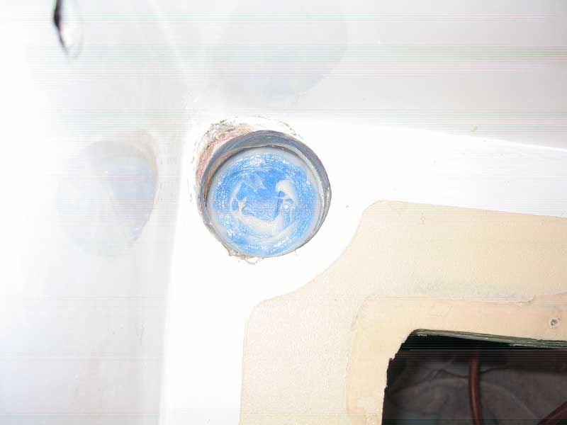
I sanded the outside of the mating surface, and cleaned thoroughly with acetone. |

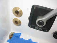
The port scupper after applying the epoxy and pressing it into place in its opening. |

Both scuppers in place. |
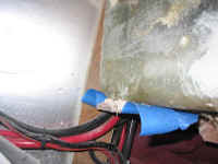
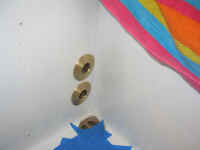
A view from beneath the port scupper, showing the fitting protruding from the backing block; the hose nipple is still
covered with tape to protect it from the epoxy. |
Sidedeck Drains
 The
two additional drains on each side--one on the sidedeck outboard of the coamings and the other in the cockpit seat forward
of the lockers--originally entered into fiberglassed fittings "Y"d into the main scupper drain beneath the
cockpit. This may have been acceptable when the boat was first delivered from the factory, but the complex tree
beneath the cockpit took up too much room, and the fiberglass was experiencing widespread failure, especially on the port
side. My new bronze scuppers made no provision for additional hoses to merge into the main drains, which was all part
of the plan. Instead, I installed new fittings in the cockpit well for each of the four sidedeck drain hoses.. The
two additional drains on each side--one on the sidedeck outboard of the coamings and the other in the cockpit seat forward
of the lockers--originally entered into fiberglassed fittings "Y"d into the main scupper drain beneath the
cockpit. This may have been acceptable when the boat was first delivered from the factory, but the complex tree
beneath the cockpit took up too much room, and the fiberglass was experiencing widespread failure, especially on the port
side. My new bronze scuppers made no provision for additional hoses to merge into the main drains, which was all part
of the plan. Instead, I installed new fittings in the cockpit well for each of the four sidedeck drain hoses.. |
 I
installed two bronze through hull fittings on each side of the cockpit well, located just above the main scupper drain
fittings at the forward end. The hoses were 1" ID, so I purchased 1" through hull fittings wit barb
integrally cast, and secured them through new holes that I cut into the well, bedding them thoroughly with 3M 101.
Drainage from these deck drains could now simply exit into the cockpit well directly above the main scuppers, which would
take care of the drainage overboard I
installed two bronze through hull fittings on each side of the cockpit well, located just above the main scupper drain
fittings at the forward end. The hoses were 1" ID, so I purchased 1" through hull fittings wit barb
integrally cast, and secured them through new holes that I cut into the well, bedding them thoroughly with 3M 101.
Drainage from these deck drains could now simply exit into the cockpit well directly above the main scuppers, which would
take care of the drainage overboard |
|
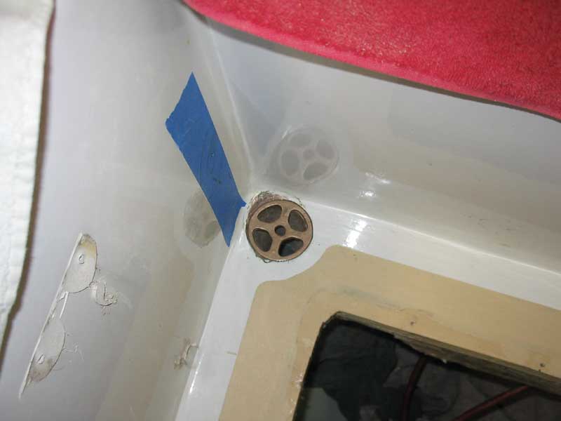
This photo shows the back side of the port drain fittings.
|
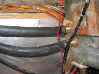
Securing the Scupper and Drain Hoses
Despite the new fittings and improved clearance, installing new scupper hoses was still an exercise in frustration; in
the end, I worked on the main scupper hoses over a period of 4 days before finally succeeding.
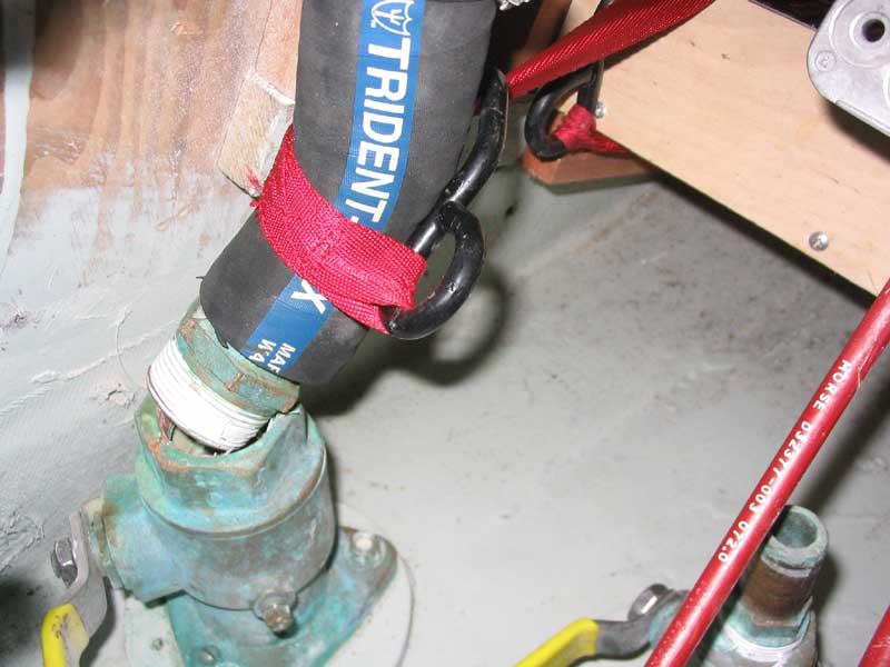
Complicating the matter somewhat--though this was completely foreseen up front and taken into
account--was the fact that the bronze scupper drains were actually designed to accept 1-5/8" hose, while the through
hulls were for 1-1/2" hose. I was aware of this before ordering the fittings, and before I installed them in the
boat I tested with a scrap of the same 1-1/2" hose I planned to use, just to make sure I could get the hose on the
larger fitting without too much of a problem. I could, but it certainly was less easy than it would be in an ideal
world. But since when does working on a boat have anything to do with the ideal world, anyway?
 In
the event, I first attempted to connect the through hulls and scupper fittings with relatively short lengths of hose, making
the runs as straight as possible. Stubbornly, I fought the hoses in this manner over a period of three days, before
finally admitting defeat. There was simply no way (at least with the access I had) that the heavy wall,
wire-reinforced exhaust hose was going to make the contortions needed to connect at both ends. I tried everything,
from every possible angle. (Fortunately, I had the large cockpit hatch;
this job would have been near impossible without it.) I tried slightly differing lengths--a bit longer, a bit
shorter. I tried attaching the top end first, then the bottom (through hull) end; I tried the opposite. I even
tried torquing the stiff hose into the proper position with a complex system of webbed ratchets, hoping to pull the top this
way and the bottom that way, to form the rough "S" shape needed. I almost thought this ridiculous effort was
to succeed, but in the end it too failed. I even tried removing the tailpiece from the seacock, installed it on the
hose, and then tried to get the threads of the tailpiece lined up with and started in the seacock, but this didn't work at
all. In
the event, I first attempted to connect the through hulls and scupper fittings with relatively short lengths of hose, making
the runs as straight as possible. Stubbornly, I fought the hoses in this manner over a period of three days, before
finally admitting defeat. There was simply no way (at least with the access I had) that the heavy wall,
wire-reinforced exhaust hose was going to make the contortions needed to connect at both ends. I tried everything,
from every possible angle. (Fortunately, I had the large cockpit hatch;
this job would have been near impossible without it.) I tried slightly differing lengths--a bit longer, a bit
shorter. I tried attaching the top end first, then the bottom (through hull) end; I tried the opposite. I even
tried torquing the stiff hose into the proper position with a complex system of webbed ratchets, hoping to pull the top this
way and the bottom that way, to form the rough "S" shape needed. I almost thought this ridiculous effort was
to succeed, but in the end it too failed. I even tried removing the tailpiece from the seacock, installed it on the
hose, and then tried to get the threads of the tailpiece lined up with and started in the seacock, but this didn't work at
all.
|
 By
then, I had wasted three days working on the hoses, all to no avail, and had exhausted (no pun intended) my supply of the
1-1/2" exhaust hose that I had on hand. It was obvious that I would have to use longer lengths of hose and create
a loop-the-loop effect in order to secure both ends. I went to the store and bought 6' of wire reinforced exhaust
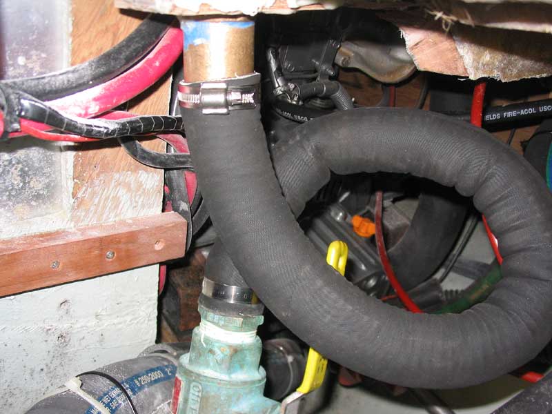
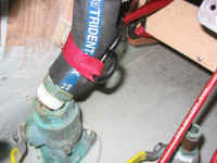
hose, which I figured would be more than enough to complete the job, with some to spare. The new hose, Shieldsflex 250
exhaust hose, was thinner-walled than the Trident hose I had been using earlier, and seemed more flexible. I liked
what I saw, and, back at the boat, thought I might give the short, direct-hose route one more go. I had plenty of
hose, so I cut off an appropriate length and gave it a try. Nope. I decided not to even waste any appreciable
time trying to make it work. Instead, I moved on to the next plan, which was to use longer lengths to loop around. By
then, I had wasted three days working on the hoses, all to no avail, and had exhausted (no pun intended) my supply of the
1-1/2" exhaust hose that I had on hand. It was obvious that I would have to use longer lengths of hose and create
a loop-the-loop effect in order to secure both ends. I went to the store and bought 6' of wire reinforced exhaust
hose, which I figured would be more than enough to complete the job, with some to spare. The new hose, Shieldsflex 250
exhaust hose, was thinner-walled than the Trident hose I had been using earlier, and seemed more flexible. I liked
what I saw, and, back at the boat, thought I might give the short, direct-hose route one more go. I had plenty of
hose, so I cut off an appropriate length and gave it a try. Nope. I decided not to even waste any appreciable
time trying to make it work. Instead, I moved on to the next plan, which was to use longer lengths to loop around.
|
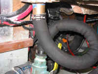
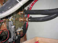
 Other
than some difficulty getting the new hose onto the bronze scuppers (it seemed to be slightly less stretchy in this manner,
but eventually I got it on enough to clamp securely), the new plan worked well, and soon I had both sides securely
fastened. The looped hoses will likely drain a bit slower than if they were straight, but they will still drain just
fine--and 1-1/2" hose and fittings are abundantly sized for this size cockpit to begin with, so there's a fudge factor
built in to begin with. I poured some water through, and was pleased when I heard it splatter on the floor beneath the
boat. (Not that I really doubted the hoses would work, but still...) Other
than some difficulty getting the new hose onto the bronze scuppers (it seemed to be slightly less stretchy in this manner,
but eventually I got it on enough to clamp securely), the new plan worked well, and soon I had both sides securely
fastened. The looped hoses will likely drain a bit slower than if they were straight, but they will still drain just
fine--and 1-1/2" hose and fittings are abundantly sized for this size cockpit to begin with, so there's a fudge factor
built in to begin with. I poured some water through, and was pleased when I heard it splatter on the floor beneath the
boat. (Not that I really doubted the hoses would work, but still...)
|
|

They work!
|
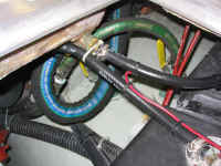
After the scupper hose debacle, reinstalling the four deck drain hoses to the new bronze
fittings into the cockpit well was a breeze. Because the new fittings are higher up than the old ones beneath the
cockpit, I cut each hose shorter by a few inches--whatever was appropriate by eye--and secured them to the barbed fittings
with AWAB hose clamps.
Project complete!
UPDATE: June, 2004
The curved, contorted scupper hoses did not work properly with the boat
in the water. At best, they allowed the water to drain very
slowly; at worst, they formed water traps, prevented rainwater from
exiting the cockpit, and even allowed seawater in, to a small extent,
when the boat was at the mooring. Unacceptable, of course.
After about three weeks in the water, I finally determined to fix the
problem once and for all. Click here to
read about the improvement.
|
|
Port and starboard (respectively) deck drain hoses connected to the new fittings
|
|